Now that the sound card interface finally seems to be working ok, I’m contemplating the merits of tearing it apart and playing with the component layout to make things more compact. It’s not exactly sprawling across the perfboard, but the component spacing can be reduced and there are a few places where I see that I can compress things a little more by changing the arrangement of some of the components. It’s certainly functional the way it is, but the mildly obssessive tweaker in me wants to keep optimizing the component placement for minimum size.
I should probably spend some more time playing with it before I take it apart.
After some troubleshooting and help from Jason/NT7S and Robert/AK6L, the problem turned out to be the transformers. Apparently they were step up/step down transformers and not the 1:1 transformers I really needed. Ordered some new transformers from Mouser and put them on when they arrived.
Still ran into problems getting the radio to transmit a signal, but after a closer examination of the board, I discovered I had connected one of my ground wires to the wrong spot so the audio signal to the radio ended up going to ground instead of the radio. Duh.
Fixed that, connected everything up and was able to make my first digimode QSO using the new interface with KC8MGD up in Michigan. From where he was, I had a good signal and wasn’t splattering across the band, so that’s a good sign.
So excited that I got this working! Now I can work on either coming up with an enclosure for this prototype board or build v0.3 and try to make it more compact. I have two more transformers that I can use to build a second interface, which I might save for later once I’m finished messing with this prototype board. I think I’ll try to find some PS2/mini-DIN6 sockets so that I can plug/unplug cables to it and get a little more flexibility about what I can plug into the board.
Every ham needs a dummy load, right? I’ve been wanting to build a small little dummy load for QRP for a while so it became one of my day-off projects today. The dummy load kit from Hendricks QRP Kits served as my model for this build.
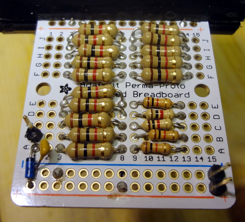
I emptied my inventory of 1kΩ 1/2W resistors and scrounged up 5 more 1kΩ 1/4W resistors out of the bag of goodies from Jason/NT7S (saved me a trip to Radio Shack). A total of 20 resistors went into the dummy load: 15 1/2W and 5 1/4W for a total theoretical power dissipation of 8.25W.
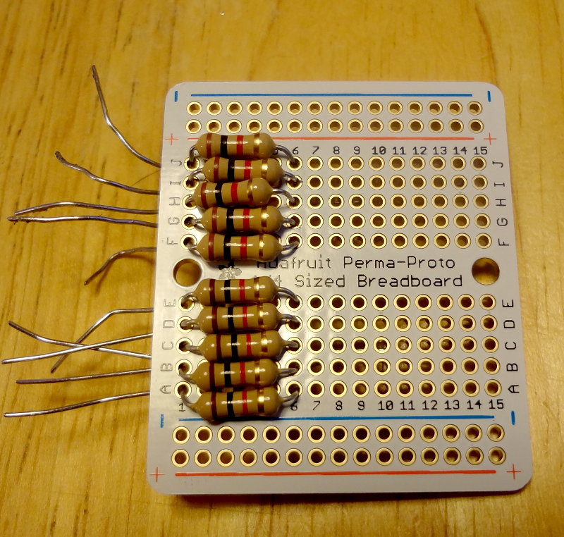
The platform for my dummy load is an Adafruit quarter size Perma-Proto board which I’ve really enjoyed working with. Here it is with half of the resistors placed on the board, but not soldered in yet.
Dummy load half complete
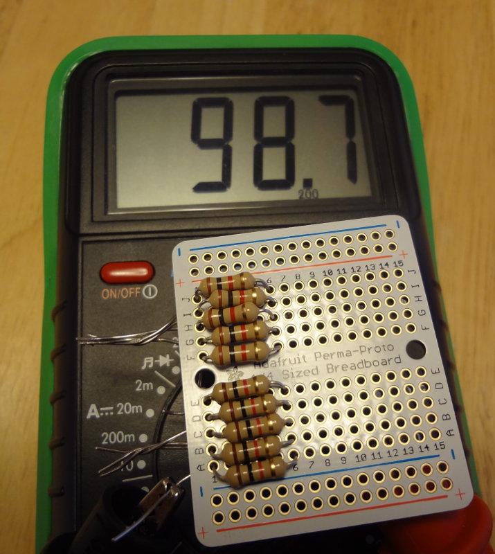
Just under 100Ω with half the resistors in, so my layout is working.
Almost 100 ohms!
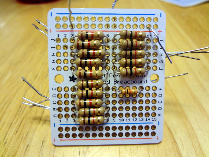
It was a bit of a squeeze to get those 1/2W resistors in, but it worked. The 1/4W resistors fit easier into each row.
Tight fit
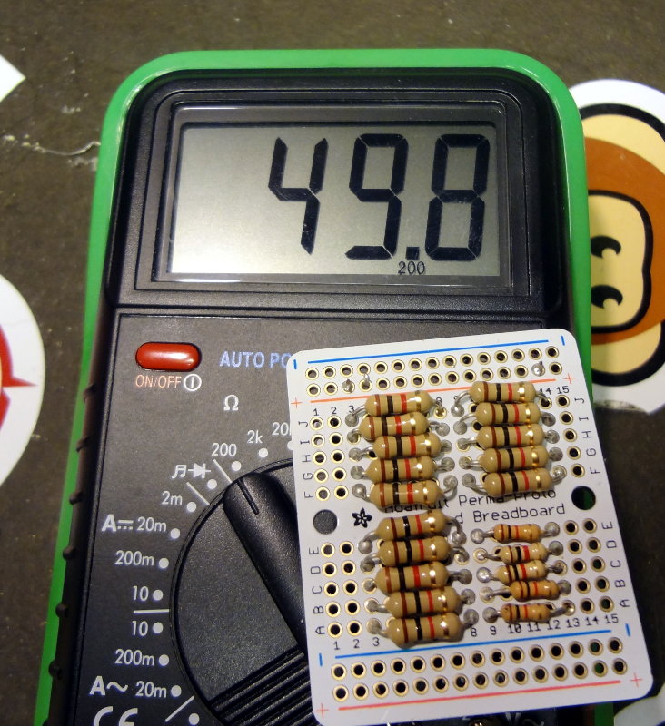
With everything soldered into place, I measure just under 50Ω. Pretty good.
Pretty close to 50 ohms
The Hendricks dummy load also lets you use measure power output using a volt meter so I added that part in as well. A 1N5711 diode (again from the bag of goodies from Jason), a 10 nF cap and some header pins finishes the dummy load.
Completed dummy load
The two pins at the lower right of the board are for the connection to the radio, and the single pin on the left side is the voltage/power measurement point. All that remains now is to find an enclosure to put it in and add a convenient way to connect to the radio and access the measuring points.
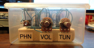
I thought the CRX1 fit pretty nicely in that parts bin, so I decided to make it into a container (can’t really call it an enclosure) for the board. It’s not an elegant enclosure like the kind Dave/AA7EE makes, but it works out pretty well, and shows off the board nicely. Maybe when I get some enclosure making skill levels, I’ll make a new one.
CRX1 container
I was originally going to get some standoffs to secure the board to the bin, but then I thought it might be nice for there to be a bit of weight so that it would sit a little more securely. I cut a piece of 1×3″ board to fit and screwed it to the bin, then screwed the CRX1 to the board.
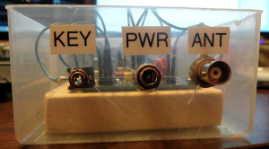
CRX1 side
CRX1 side
Now I need to find some rubber feet for the bottom of the bin and some knobs for the gain and tuning pots.
Still don’t know if any of my signals are making it out of the radio.
Using headphones, I can hear the sounds fldigi generates in response to the text I “transmit”, so I know there’s stuff coming out of the laptop. The radio goes into transmit mode, but there’s no activity on any of the meters so I can’t tell if anything is actually being transmitted.
Matthew/W2MDW suggested using pskreporter.info to see if I get spotted. After sending out a bunch of CQs, test messages and trying to respond to someone’s PSK31 signal, it didn’t appear that any of the listening stations heard my signal as far as I could see.
The data port pinout for the TS-480 has pin 2 as the audio signal ground, which is unconnected in the PS2 cable I’m using. I wonder if that could be messing up the audio that’s going into the radio.
Update: I can see there’s about 70 mVAC of signal going out of the interface into the radio, so at least there’s something getting to the radio. Not sure how much needs to be going into the data port to make the radio send stuff.