ARRL Handbooks from 1953 and 1959 are the two most recent additions to the collection. I’m just a custodian for these two handbooks though, because they really belong to the club. I don’t know if anybody from the club will ever ask for them but until then, they’ll have a good home with the rest of the collection.
Front cover of the 1953 30th edition ARRL HandbookFront cover of the 1959 36th edition ARRL Handbook
They’re in fairly decent condition for their age (73 and 67 years respectively) with the usual wear and tear from use along the spines.
The name of a former owner, William E Horton, is written (with very nice penmanship) on the inside title page of the 1953 Handbook. The rest of the book doesn’t have any other unusual writings or features in it.
The lower half of the 1959 handbook’s spine is blacked out with black marker for some reason.
ARRL Handbooks from the 1950s: 1950, 1953, 1956, 1959
The 1959 Handbook also has the name, street address (no city or state though), and phone number of a previous owner, Charlie Gober, written inside the front cover. The inside cover also has a section blacked out with a marker. The words “University Library” (possibly a library stamp) are faintly visible in the blacked out area.
Blacked out area inside the front cover of the 1959 ARRL HandbookColour enhanced area of the blacked out region on the inside front cover of the 1959 ARRL Handbook
The collection now has 4 handbooks from the 1950s, which ties with the 1970s for the most number of handbooks in each decade.
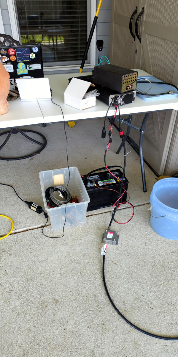
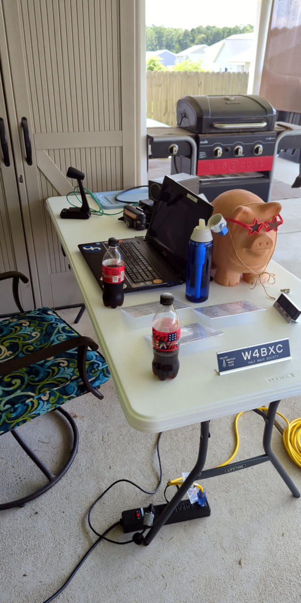
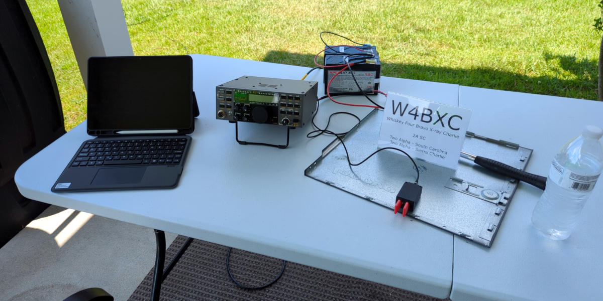
For Field Day 2026, W4BXC operated for the first time with two transmitters (2A SC): the TS-480SAT, and an Elecraft K2.
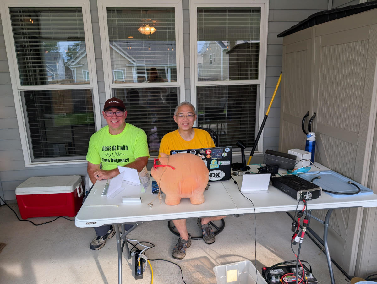
W4BXC Field Day 2026 phone stationW4BXC Field Day 2026 phone stationW4BXC Field Day 2026 CW station
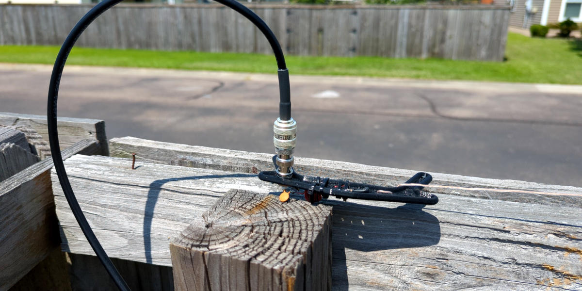
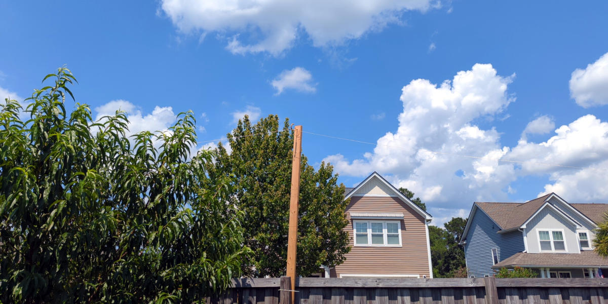
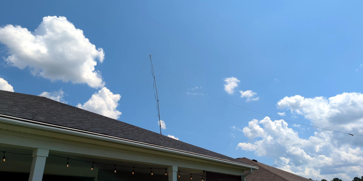
A 66 foot long end fed half wave QRP antenna was assembled for the K2 and set up in an inverted V configuration with the center supported by a 8-ish foot long 2×4 zip-tied to a fence post putting the top of the antenna about 12 feet in the air.
The K2 was operated by Jason as the CW station while I was on the TS-480 doing SSB, both operating off battery power. The K2 ran the whole day pretty easily on 2 7Ah former UPS batteries, and the TS-480 was on a new deep cycle marine 109 Ah battery (the three batteries that were used for previous Field Days died sometime over the past winter).
W4BXC Field Day 2026 EFHW antenna feed pointW4BXC Field Day 2026 EFHW antennaW4BXC Field Day 2026 dipole antenna
The Morgan Systems 20m and 40m band pass filters purchased from KF7P did an excellent job keeping the two radios from interfering with each other.
This year we finished Field Day with a total of 162 QSOs, 80 on CW and 82 SSB contacts. Not as many phone contacts as last year but thanks to Jason operating CW, 39 more total contacts than the previous year. Bonus points were claimed for being on emergency power (200 points), me acting as safety officer (100 points), and online submission (50 points). By my count, W4BXC’s total score should be ((80*2) + 82)*2 + 200 + 100 + 50 = 834 points.
After my recent acquisition of the Hallicrafters HT-32, a thought popped into my head: What does the boat anchor/vintage radio of the future look like.
Go to any hamfest or talk to any long time amateur radio operator, and it won’t be hard to find 40+ year old radios still in working condition (some better than others). Even if they’re not working, it’s not impossible in most cases to find parts to resurrect the radio.
I’ve got 3 Hammarlunds and 1 Hallicrafters in my boat anchor collection now. Our Kenwood TS-480SAT or Elecraft K2 could be considered vintage, depending on what time frame for vintage you want to use. Should they be considered part of the boat anchor collection?
In the age of (current) modern, IC based, software-defined radios (pretty much anything from 2010 onward), how many of those will remain servicable/fixable enough to become the boat anchors of the future? Will anybody be using an ICOM IC-7300/7300MK2 or Yaesu FTDX-10 in 2050? Will I be able to repair our Kenwood TS-480SAT in 2040 when something fails?
Ask anyone of a certain ham radio age what a boat anchor radio would be, and you’ll get answers like Drake, Collins, Hallicrafters, Hammarlund, National. What will people say in 2040 or 2050? What boat anchor radios be we be using 20-30 years from now?
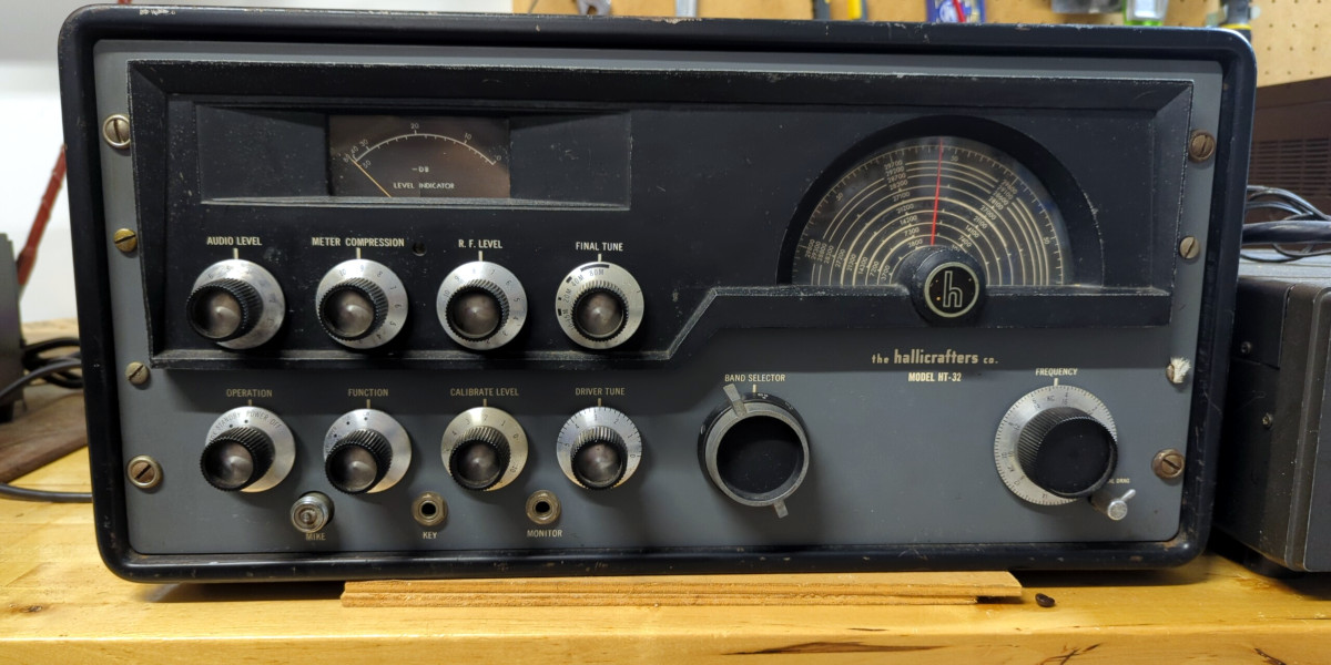
Joining the vintage radio collection this week is a Hallicrafters HT-32 Mark I transmitter I acquired from a local ham who wanted to see it go to someone who would put it back on the air.
The HT-32 works on 5 bands (80, 40, 20, 15, 11/10m selectable by crystal), does SSB, CW, and DSB (double side band, AM without the carrier). Maximum power output is 100 W in SSB/CW mode and 25 W in DSB mode.
An old Hallicrafters HT-32 amateur radio transmitter sitting on a workbench
At 50.7 cm (W) x 25.6 cm (H) x 43 cm (D) and weighing in at just under 40 kg, this radio is a BIG HEFTY beast. This is the kind of radio where you set it down somewhere in the house and built your shack around it. None of this “Oh, maybe I’ll move it over to this side of the room”. No. Once you’ve set it down that’s where it’s staying.
When I arrived to pick it up, the previous owner had it plugged in with a light bulb connected to the antenna connector for a dummy load. Everything seems to be in working order, and there was enough RF output coming through the antenna connector to light up the light bulb. The brightness of the light bulb modulated nicely when he spoke into the microphone, so that seemed like a good sign. Wasn’t able to verify what the transmitted RF sounded like, but once I get it on the air I’ll find out soon enough. The previous owner mentioned he had done a full alignment on the receiver, but that was quite a while ago. Hopefully nothing has drifted or changed in the meantime.
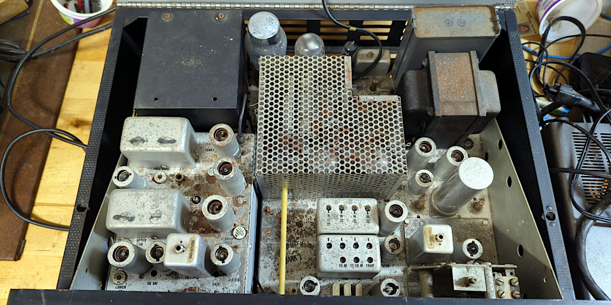
The radio is in pretty good condition for its age, with some light surface corrosion (what 70 year old radio wouldn’t). The top metal mesh cover flips open to reveal an assortment of tubes, capacitors, tuned inductors, and a big chunky transformer.
Under the Hallicrafters HT-32 lid
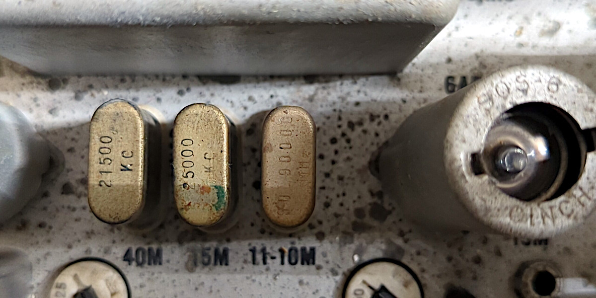
One of the three crystals in the radio can be used to set up the HT-32 to work in either the 11 m (CB now) or 10 m band.
Three crystals in the Hallicrafters HT-32. The crystals are marked 21500 kcycles, 25000 kcycles, and 30.9 MHz.
The crystals are used to mix the SSB signal from the second mixer stage to produce the output frequency for that crystal’s band. The 11-10 m crystal can be switched out for operation in the 11 m band, or different 500 kHz segments of the 10 m band. The radio currently has a 30.9 MHz crystal which sets the radio up for operating in the 11 m band (26.96 – 27.23 MHz).
I haven’t pulled the radio out of the chassis yet to see how things look underneath. I expect that the rest of the radio will look fairly similar to the top.
I’ll have to figure out how to wire up a microphone to the radio. It looks similar to the connectors on the Heathkit IG-102 that I replaced with BNC connectors. A bit of research tells me that it’s an Amphenol 75-MC1F/Switchcraft 2501 connector. Wonder if I can find a working microphone with one of these connectors on it already.
Fortunately it also came with the manual, which I promptly scanned and made into a PDF. The manual also conveniently has the schematic for the radio. I’ll have to spend some time studying the manual to learn how to use it before I try to get this paired up with one of the Hammarlunds and get it on the air.
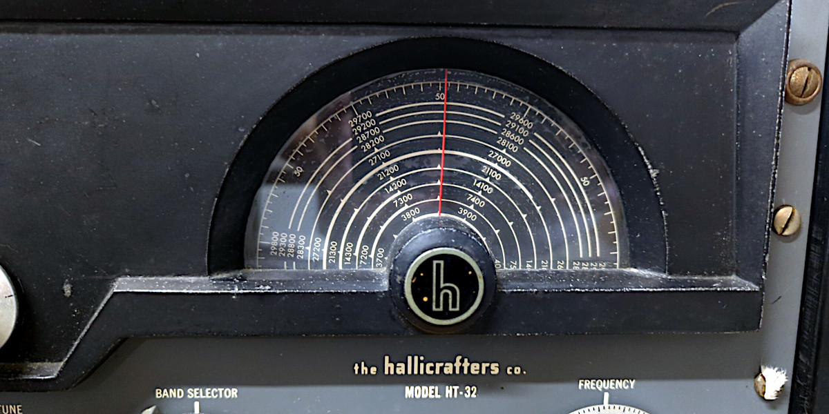
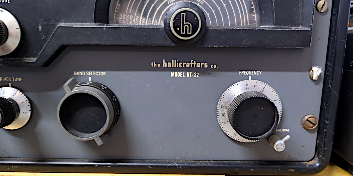
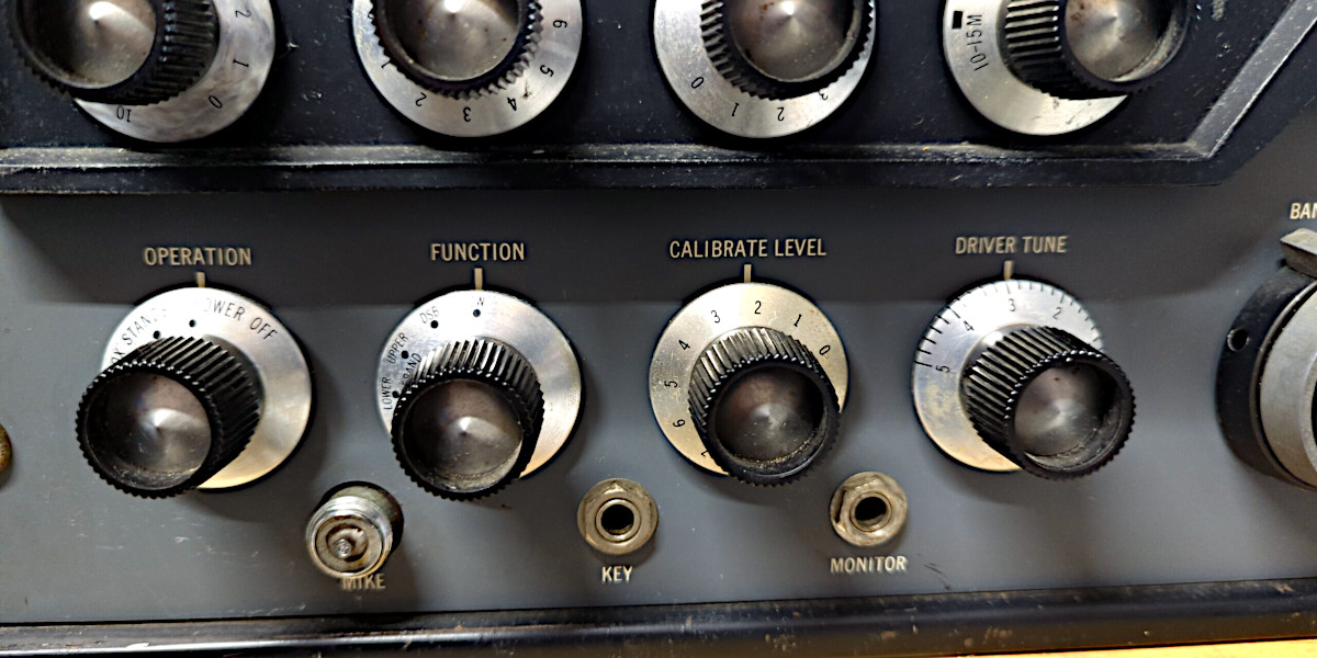
Hallicrafters HT-32 frequency dialBottom right of the Hallicrafters HT-32 frornt panel showing the band selector knob and frequency dial knob.Lower left row of knobs on the Hallicrafters HT-32
Looking forward to getting this radio set up and working.
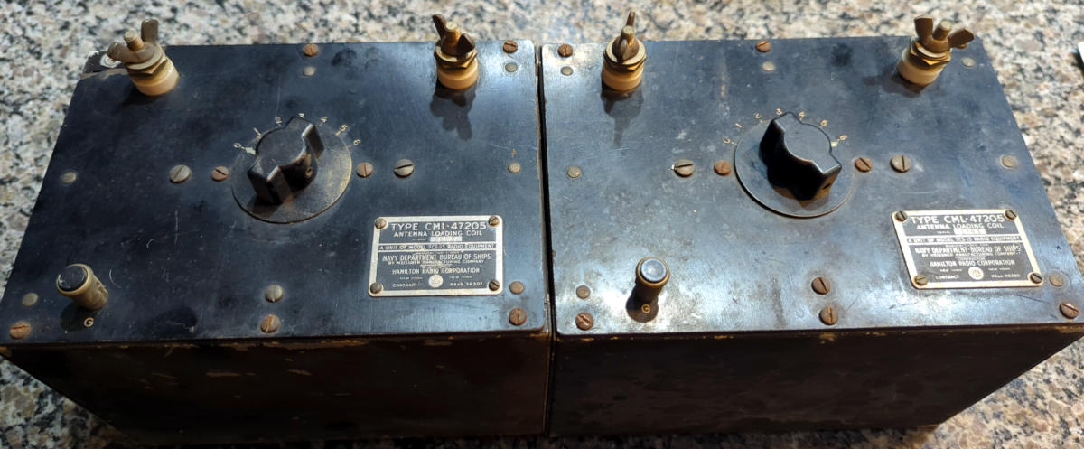
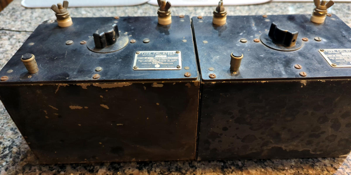
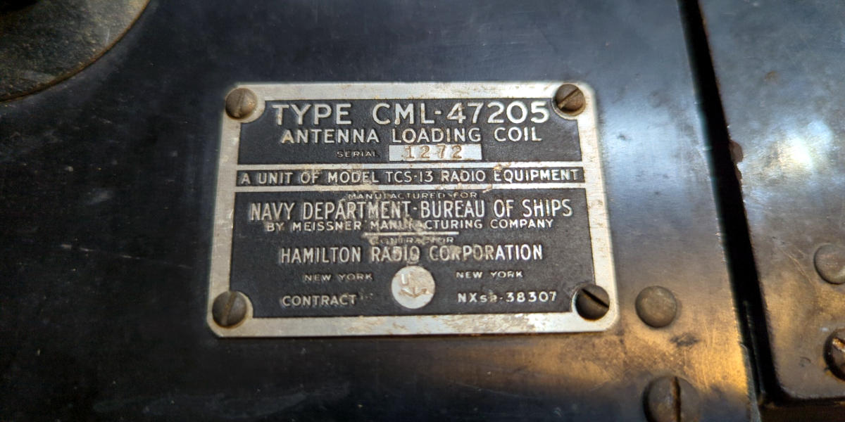
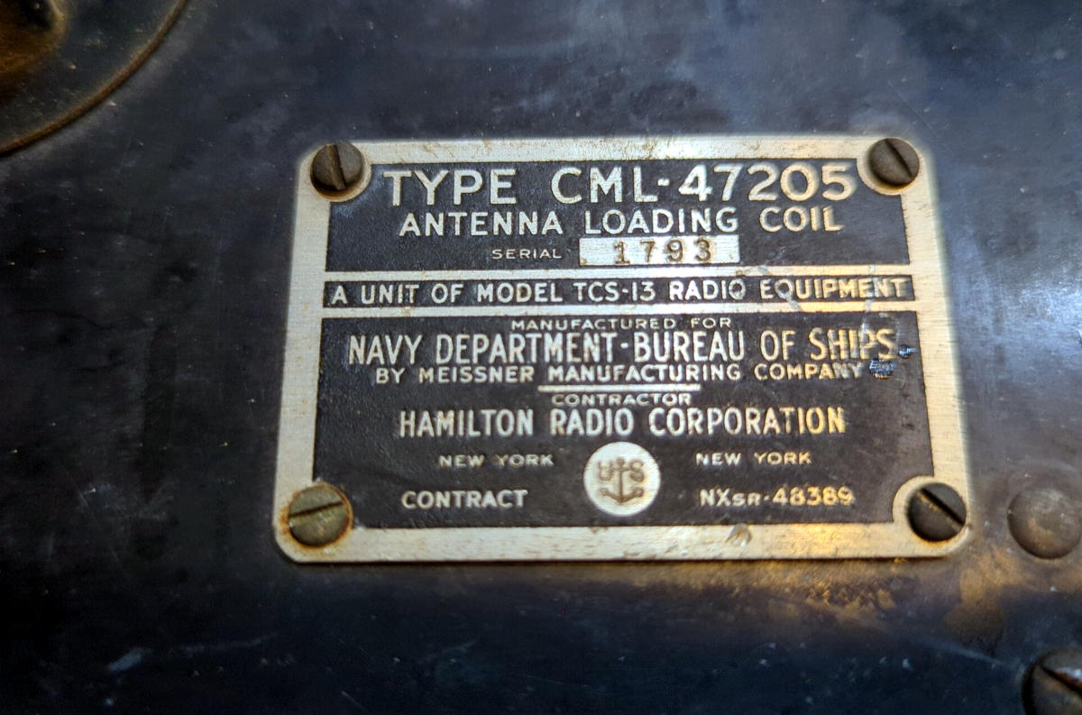
While doing a bit of clean up in the garage, I came across the CML-47205 antenna loading coil units. They came as part of a couple of US Navy TCS-13 transmitter/receivers that ended up in my collection a few years ago.
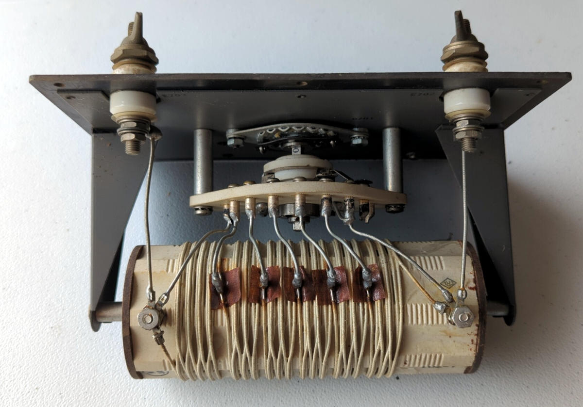
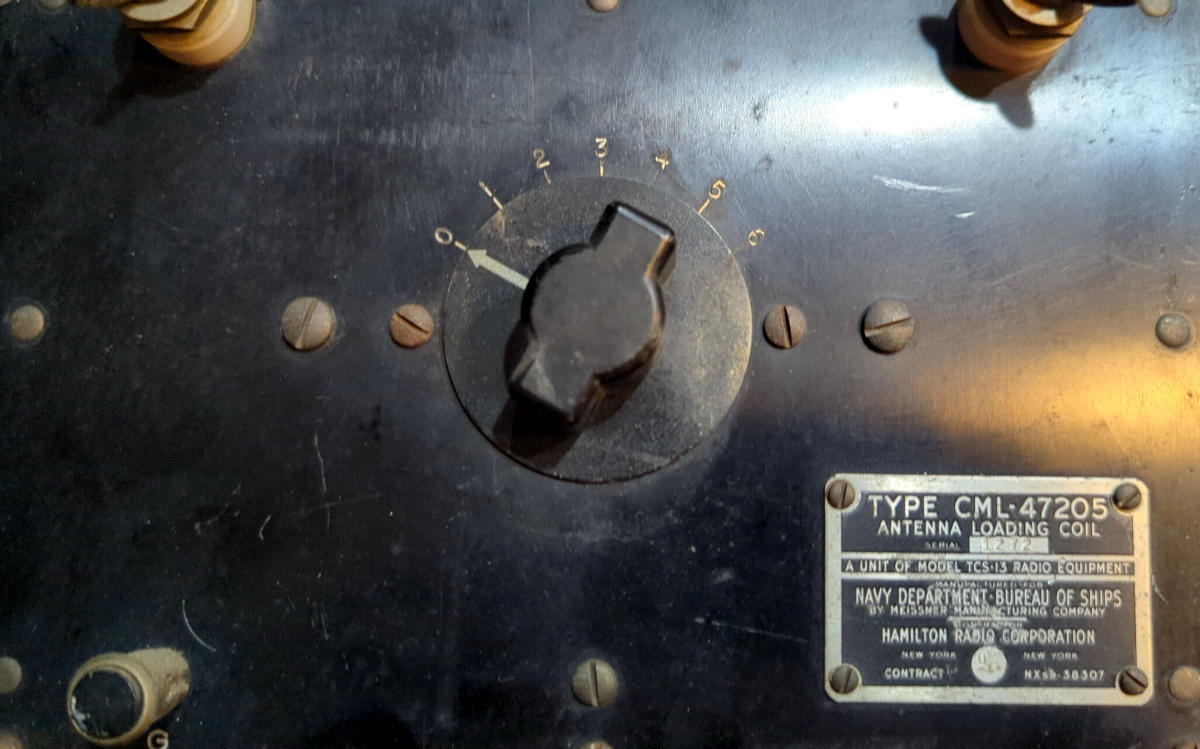
They’re simple black boxes, 6 x 8.5 x 5.75 inches with a 7 position dial switch numbered 0-6, 2 thumbscrew terminals and a ground terminal. The top cover plate appears to be a plastic/resin material (Bakelite or something similar I’m guessing) and the rest of the enclosure is metal. The corner of the top plate on one of the units was broken and the screw missing. Inside it’s pretty simple, a multiposition switch and a tapped inductor coil on a plastic form.
From the manual, it’s meant to be used with a 20 foot whip between 1.5 – 3 MHz. Dial setting 0 selects the highest inductance for the lower frequencies, while dial setting 6 selects the lowest inductance for the higher frequencies.
Using my AADE LC meter connected across the two terminals, I measured the inductance for each position.
Dial setting
Inductance (μH) SN 1272
Inductance (μH) SN 1793
0
98.32
97.76
1
76.49
75.81
2
59.08
58.57
3
41.78
41.51
4
25.83
25.53
5
12.98
12.72
6
0.46
0.38
Might be interesting to see if I can incorporate these into a vertical antenna for Field Day.