Etherkit EtherKeyer Mini printed circuit boardKM4CFT 3D printed CW paddlesKM4CFT 3D printed CW paddles
I’ll need to see if I’ve got a spare TRS cord lying around to use with the paddle.
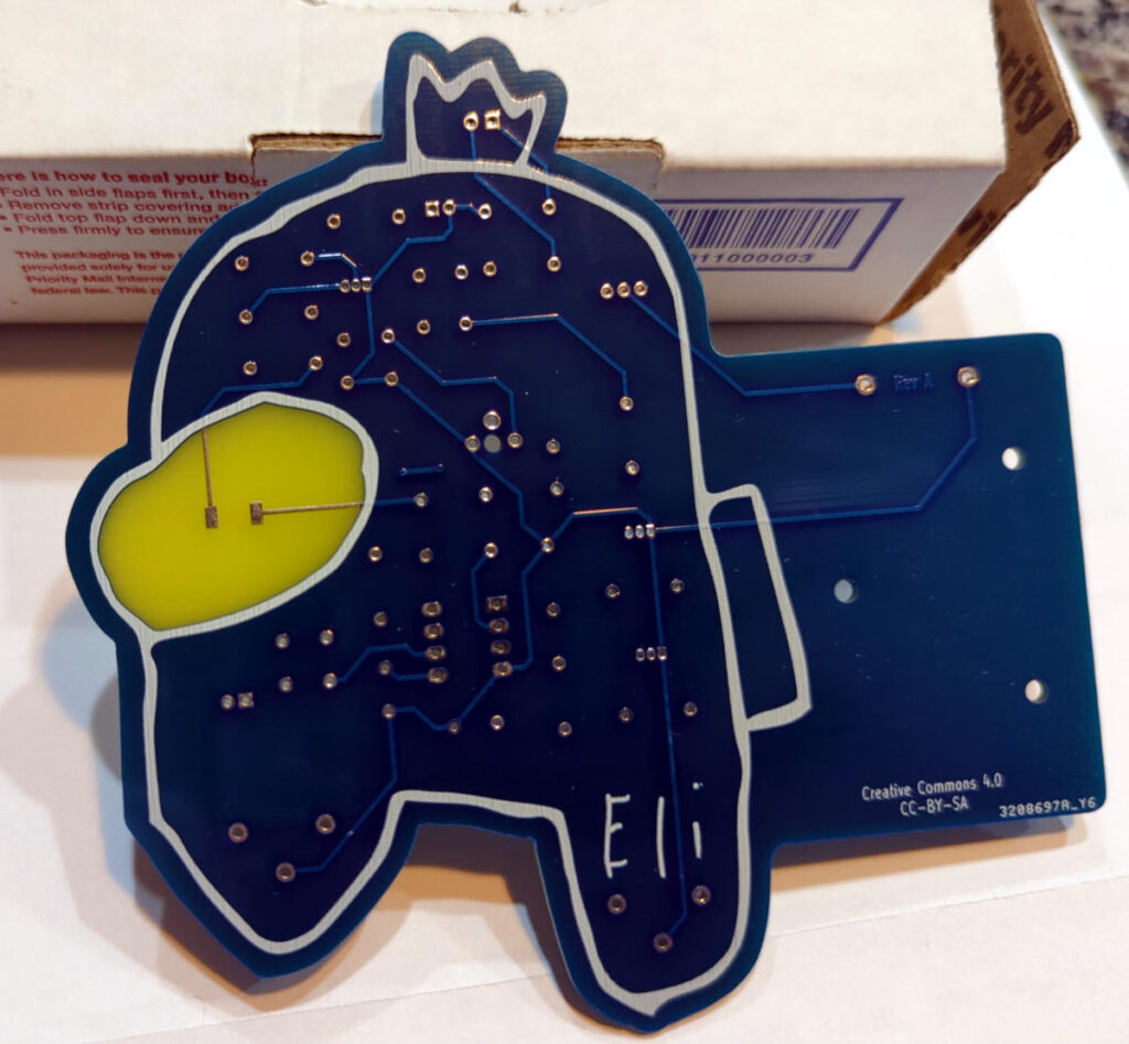
The other board he sent along was a code practice oscillator board (the Etherkit CPO Among Us edition).
Printed circuit board in the shape of a character from the video game Among UsPrinted circuit board in the shape of a character from the video game Among Us
These should make for a fun weekend project.
Jason’s got some fun looking things in the works these days. Go see what he’s been up to on his Applied Etherics Substack.
One of the items from the KB1SH collection of parts I bought at Hamcation was an unassembled frequency counter kit. A packing slip still in the box showed it was purchased from a company called S&S Engineering out of Maryland in 1993. A quick search on Google didn’t yield anything that looked like it might have been related, so the S&S Engineering that produced this kit probably isn’t around anymore.
I love assembling and soldering a good kit, and this looked like a pretty good one. Documentation included the assembly instructions as well as a circuit schematic and a brief theory of operation section. This particular kit included an option for an additional 4 digit LCD display. All the necessary parts turned out to be there, except for a TO-92 voltage regulator that could very well be buried in my carpet somewhere. I neglected to get any photos of the boxed kit, but I did remember to take photos while I was soldering parts on.
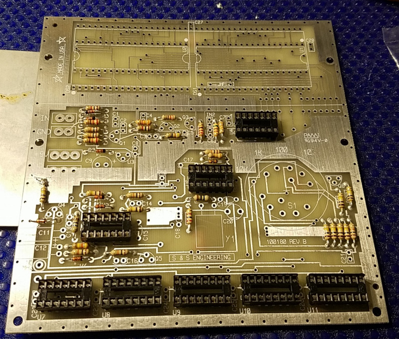
The circuit board for the counter is relatively large, 13.1×13.5 cm and the part density wasn’t high so there’s plenty of room to work on the board while soldering things on. The printed circuit board itself is etched and tinned, but without a solder mask that you’d normally see. The only problem I ran into while soldering were two parts that went into a very large ground plane/heat sink. This would have been a good point to break out the flux and switch to a larger tip on the soldering iron had I thought about it.
Partially assembled frequency counter kit from S&S Engineering
There are a total of 10 ICs in the kit, which I decided to use sockets for. 8 of the sockets and all the resistors are installed in the photo above. The other two were for the 40 pin ICs used to support the LCD displays at the top of the board.
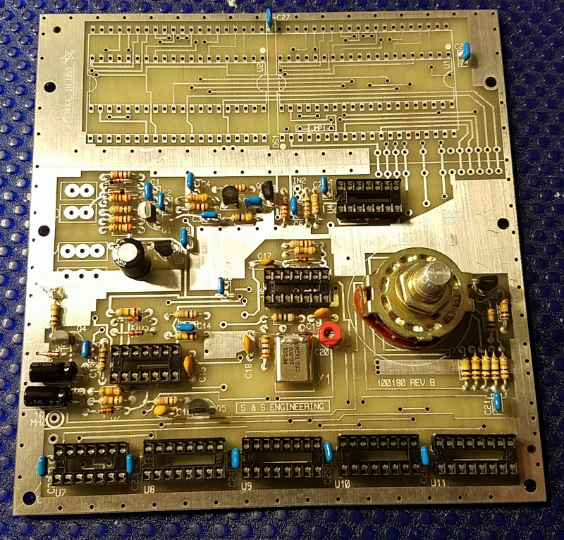
Partially assembled frequency counter kit from S&S Engineering
Above is the fully populated board, except for the two LCD driver ICs and the LCDs themselves.
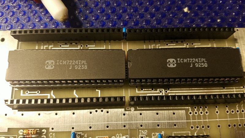
LCD driver ICs installed on the PCB with header pins for the LCD displays
The kit came with two 40 pin sockets, which the instructions say to cut apart and use for the LCD displays. I opted to use the sockets for the ICs, and some tall header sockets for the LCDs.
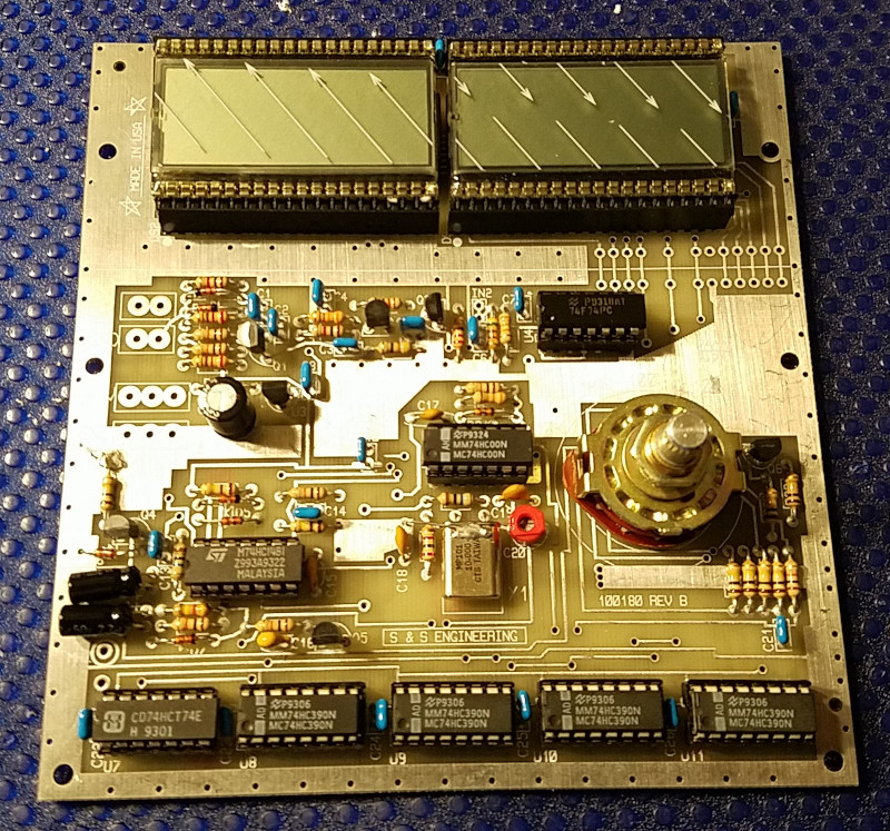
Assembled frequency counter kit from S&S Engineering
The fully assembled board looks pretty nice. Unfortunately, the frequency counter isn’t working yet. I’ve confirmed that the 10 MHz test point puts out something close to a 10 MHz signal, according to one of my DMMs. Not sure if I’ve put in something wrong, bad soldering, or if there’s just a problem with the LCD displays.
Random LCD segments showing up with power applied
A few seemingly random LCD segments show up and then eventually fade after a few minutes. This makes me think it might be an issue with the LCD displays themselves. They are almost 30 years old (at least) after all. I’ll see if I can stick them into a breadboard or something and test them out. Wonder if it would be possible to wire in some other kind of display.
Figuring out how to get this frequency counter working will be as much fun as putting it together I think.
Update: Getting closer to figuring out the problem. Turned out I had the LCD driver ICs installed upside down. I wasn’t paying close enough attention to the installation instructions. With the ICs installed properly (glad I had them in sockets), now I can get the digits to display properly if I wiggle the LCDs in the header sockets to get them into a certain position. I might need to replace the header sockets with something else.
A while back, I made a monopod to use with my camera. Handy thing to use when I don’t feel like lugging around a tripod. Also serves as a nice walking stick.
On one of my last visits to Radio Shack, I picked up two telescoping antennas thinking that I could use them as dipole elements.
Add one section of aluminum angle stock, a bulkhead BNC jack, a couple 1/2″ 4-40 screws and nuts and now I’ve got a telescoping 2m dipole antenna attachment for the monopod.
Monopod antenna attachment
It took me a while to figure out how I was going to insulate one of the telescoping elements from the angle stock. While I was studying the problem, a solution struck me: plastic wall anchor. Worked perfectly.
Tuning the antenna was a simple matter of adjusting the length of each telescoping antenna to get close to 1:1 across the 2m band.
Tuning the monopod antenna attachment
Looks pretty good. I’ll check it again outside over the weekend and try it out with the HT.
Monopod antenna attachment
If I hold it up in the air by the base of the pole, I can get the antenna about 2.5 m up in the air. I’m hoping I’ll be able to reach the two repeaters that are about 8 miles away a little better than I can with the HT antennas I already have.
I finally got around to assembling the dummy load, paddle and keyer over the past week.
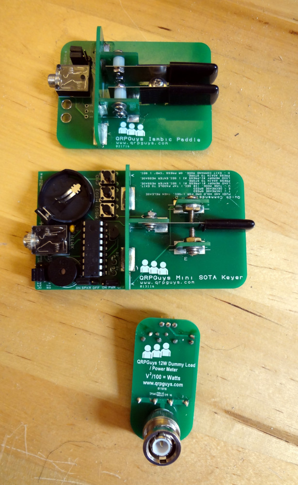
Iambic paddle, mini-keyer and dummy load from QRPGuys
The dummy load was the easiest to assemble, and parts placement was pretty obvious (I’m only a little bit bothered because the resistors don’t line up…). 5 minutes of soldering and you’ve got yourself a nice compact little 12 watt dummy load that also lets you measure power output via a voltage measurement.
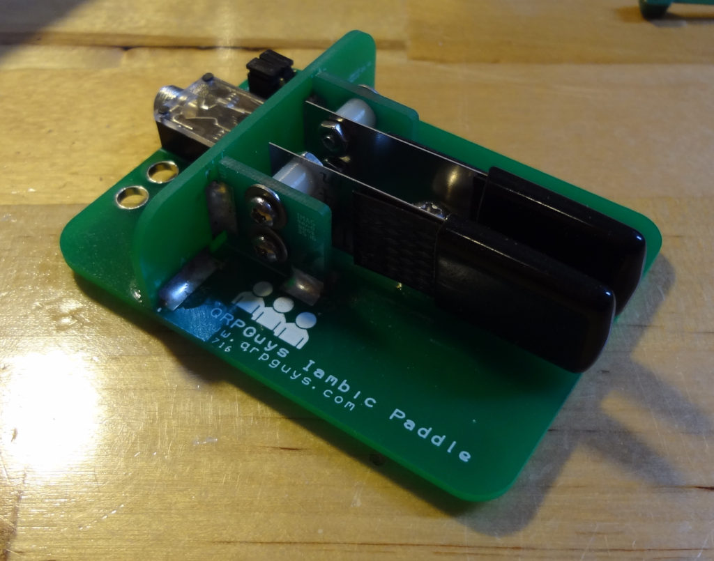
The mini-paddle was only a little more difficult because of the size and length of the screws being used to attach the paddles. Still a relatively easy build, although you have to be careful with the alignment of the little PCB pieces that are soldered onto the base. The hardest part was getting the little nuts that hold the paddles secured. There’s not a whole lot of space to work in, you have to hold the screw, spacers, washers and metal paddle part while trying to get the nut on, and there’s not a whole lot of screw remaining to get the nut started on. Moderately difficult to assemble.
In terms of parts count, the single lever keyer/paddle was the largest kit, but easier to assemble than the iambic mini-paddle. On the electronics side, the only thing I had to consult the assembly manual for was to find out the correct orientation for the 1N4148 diodes. Placement of all the other parts is pretty obvious from the silkscreen outlines. On the keyer side, assembly was similar to the mini-paddle, but with only one lever to worry about, getting it put together was significantly easier. I did end up leaving off two nuts for the two screws that serve as contacts for the paddle. With the nuts, the screws were just too far away from the paddle. I don’t know if the screws I got were just too short to begin with, or if the kitting changed but the instructions didn’t get updated.
True to their mission, these are fun, inexpensive little kits to put together. Looking forward to working on the frequency counters next.
Unlike the previous boards I bought (from the crowdfunding campaign), the latest versions now come fully assembled except for the header pins. If the thought of soldering tiny surface mount devices was keeping you from trying the breakout board, worry no more.
The 10 mW WSPR beacon app note looks pretty interesting, and I think it would be fun to try to get one set up once we’re in the new house. I’d love to see how far it could be heard.
We’ll hopefully be in the new house in a few more weeks. I’m looking forward to getting the shack and workshop set up again so I can get to playing.