From Todd/VE7BPO/@QRPHB of QRP HomeBuilder is the K3NHI sweep system that he built. He put out a call asking for people to host a zip file of his build and I offered to stash them here for him.
Inside the zip file you’ll find a description of the sweep generator, schematics, build notes and lots of pictures by Todd.
I camee across N5ESE‘s site and started browsing around some of his projects. He’s got quite the list of them. In his Gizmos section is an RF probe which looked pretty easy to build.
I had a set of those springyy hook-y grab-y DMM leads that were broken, so I cut off the spring-y hook-y grab-y part to use for the DMM side.
On the work bench was a perfectly sized piece of PCB from when I was experimenting with cutting and scoring PCB. From the RXTX build, I just happened to have some extra 0.01 μF SMD capacitors which were perfect for the job. A 1N34A diode and 4.7MΩ resistor finished off the parts.
I used a small hacksaw to score the PCB and divide it into three sections, cut out a notch for the diode and cut the head off a brass nail to serve as the probe. Soldering everything in place was pretty easy.
RF probe
Soldered on the leads and a ground wire with alligator clip and put everything into a shrink wrap tube.
RF probe covered with heat shrink tubing
The full probe, with all the leads ready for some RF to measure. I still need to find a decent enclosure to shield the probe with.
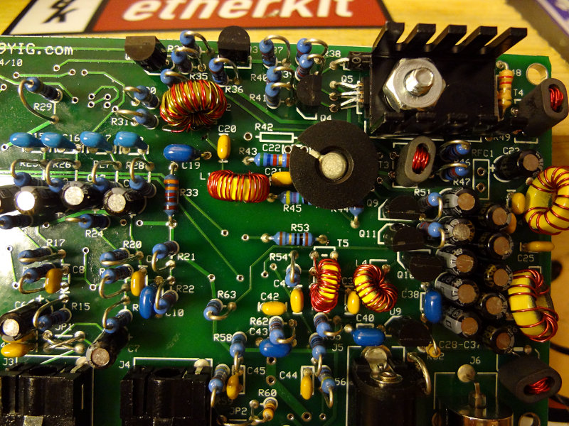
The driver/PA section is the final section of the build.
Three capacitors are the final SMD components left to solder onto the back of the board.
Capacitors for the driver/PA section
Two binocular core transformers are part of this section. You might be tempted to do these last, but I suggest making them the first components to install. The top of the board is starting to get pretty crowded at this point and you’ll want a bit of room to thread the wires for the transformers through the holes. Same for the RF choke (RFC1, which I noticed I inadvertently left out).
The transformers themselves can be tough to wind. Make sure you pull each wire tightly through the hole or you’ll have a hard time fitting all the windings in.
The three BS170 FETs get covered up by a heatsink and pad. The 2N2222 transistor also gets a heatsink treatment. There are a few components that get partially covered up by the heatsinks, so make the FETs and 2N2222 the last parts you work on.
Everything else is pretty simple and should go together without any issues.
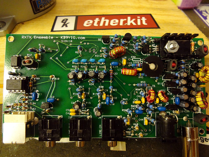
Ensemble RXTX driver/PA section
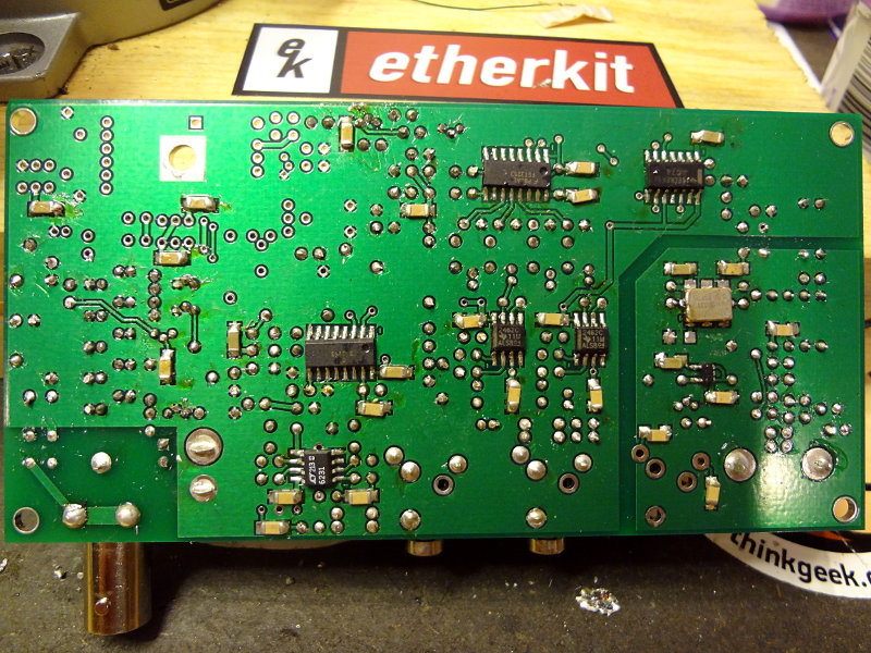
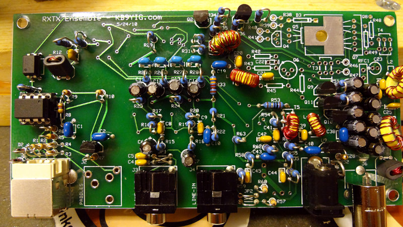
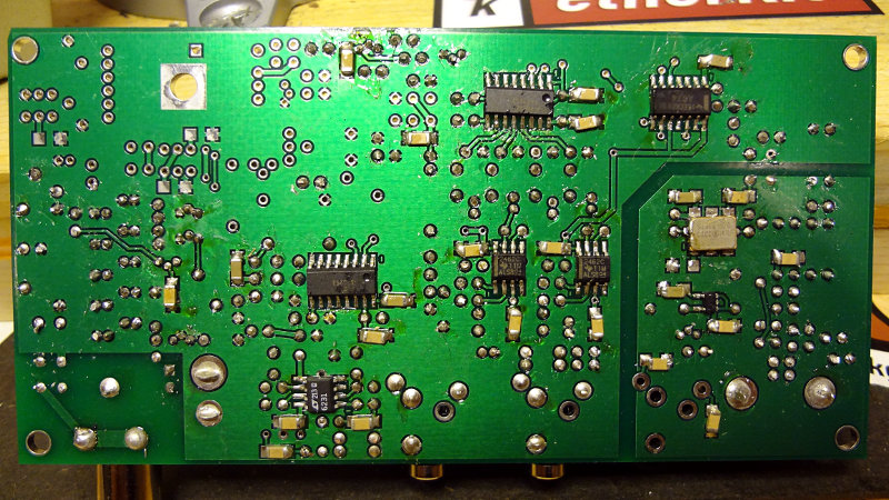
The top and bottom of the (practically) completed board.
The TX mixer section doesn’t have quite as many components as the previous section, but there are a few band specific components including a toroid and transformer so you’ll want to make sure you have the right band selected if you’re following the WB5RVZ build instructions.
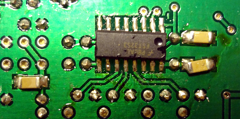
Like the RF mixer stage, the only SMD components are the FST3253 IC and three accompanying capacitors.
Ensemble RXTX TX mixer
The through hole components consist of a 3904 transistor and a few capacitors and resistors. Watch out for accidental solder bridges between the closely spaced holes of the transistor.
Both the L1 inductor and T2 transformer have a lot of turns to wind onto a relatively small T30 core. If you have some 28 or 30 gauge magnet wire that’s a different colour than what comes in the kit, use it for either the primary or secondary winding on T2. That will help make it easier to separate out the T2 wires before soldering onto the board.
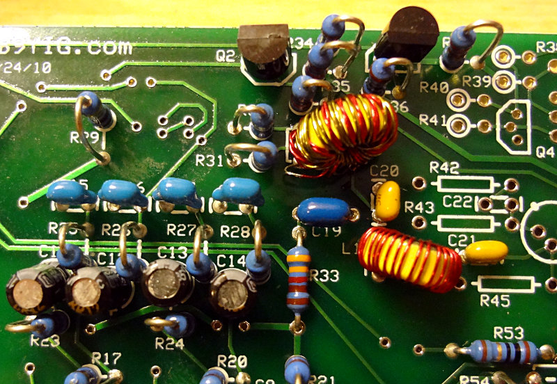
Lots of parts to solder on in the TX op amp section, but most of them are through hole. No band specific compnents to worry about.
You might be tempted to place them all at once and then start soldering, but with all the dangling leads you end up with, it can make getting around with the solder and soldering iron a bit difficult. I found it easier to place a few components, solder, trim the leads and then repeat with a few more components.
I cross-wired JP1 here instead of jumpering them straight across, based on the notes in the build instructions. May end up having to change this, but we’ll see.
Ensemble RXTX TX opamps top
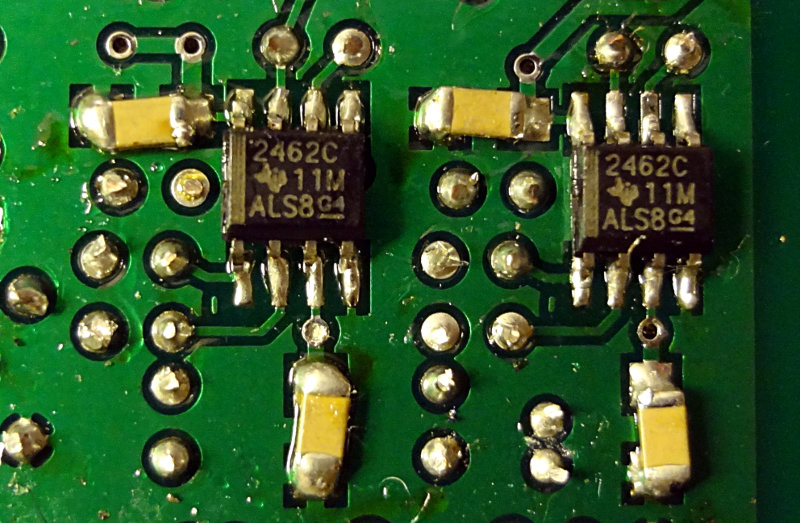
Two SMD op amps and accompanying capacitors go on the bottom of the board. By now, soldering the SMD components should be pretty easy, even if you’re new at working with them.
Ensemble RXTX TX opamps section bottom
Getting near the end of the build now. Only two more sections left: the TX mixer and PA. TX mixer section is up next.