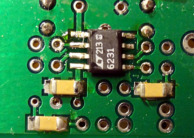
The RX op amp/output stage is another relatively easy one. A handful of non-band specific through hole parts, 3 SMD caps and the SMD op amp. Nothing too difficult here, although again, you’re dealing with pretty tight quarters with the through hole parts.
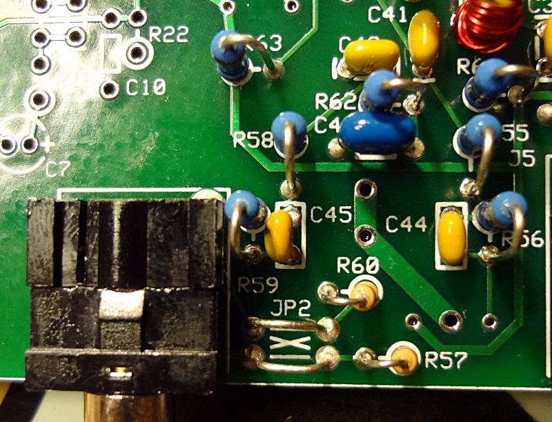
The line-in (which goes to the line in port on your computer’s sound card) is the largest component to deal with.
The instructions for wiring JP2 in the build instructions were a bit confusing. My interpretation was that if your jumpers crossed over (jumper wires formed an X), then you could use any of the software mentioned (PowerSDR, Rocky, Winrad). In this configuration, you’d need to set a “Swap IQ” setting in Rocky/Winrad. If the jumpers were straight across, you could use Rocky or Winrad, but not PowerSDR.
I chose to jumper them straight across as shown in the WB5RVZ build instructions.
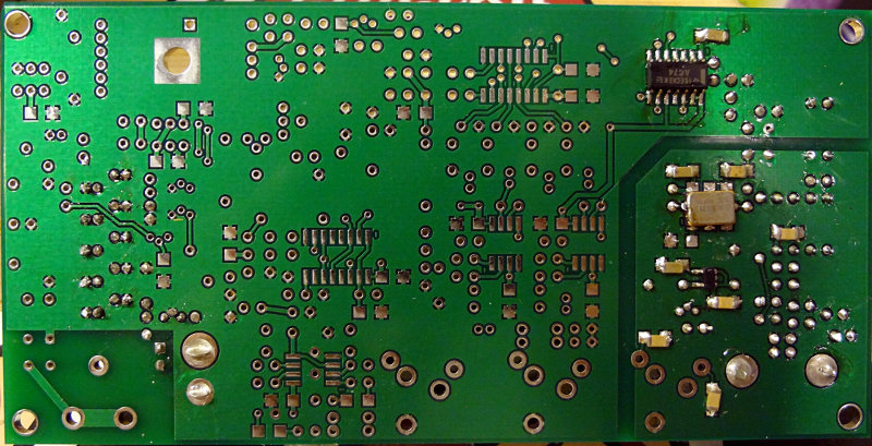
Top of the board for this section.
Bottom of the board
Next section is the TX op amp. Lots of parts there.