Although the 3.3V voltage regulator seems to be dead, I decided to press on with the build. So far, this RXTX kit is proving to be one of the more challenging ones I’ve done so far. Lots of parts, small-ish components and closely spaced holes for the through-hole parts.
On to the local oscillator section today. The most challenging part in this section is the Si570 oscillator chip. The pads for pins 1-6 are pretty large and easy to solder. Pins 7 and 8 on the sides of the oscillator have pretty tiny pads though. This means it’s pretty important to position the Si570 properly. There’s plenty of room to position the Si570 up and down, but too much to one side and you end up covering up the pad for either pin 7 or 8. Cover them up too much and you may not be able to make the connection between the oscillator and the pad. I think with mine, I may have a dodgy connection at pin 7. I’ll probably find out in a little while once I get around to replacing that voltage regulator.
Also I forgot about leaving off C55, so I’ll have to take that off when I get back to working on the board.
The rest of the local oscillator section was a few more surface mount capacitors and through hole components. The first of many transformers and toroids is in this section too. Pretty easy, although a little bit of a challenge with the close hole spacing. You definitely want to use a small pointy soldering iron tip for this kit.
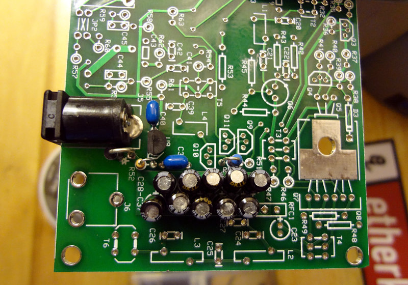
The top and bottom of the board so far.