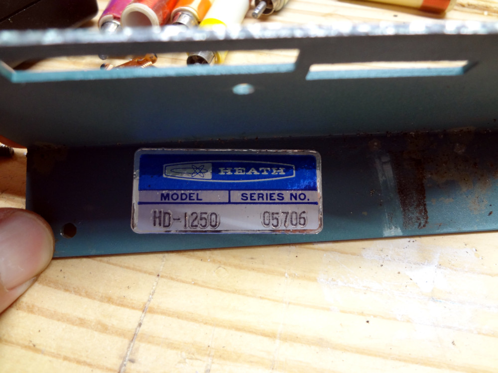
The Heathkit HD-1250 grid dip meter (SN 05706) I acquired at the hamfest a few months ago looked in decent condition aside from some pretty major foam rot.

Heathkit HD-1250 grid dip meter 
Nasty case of foam rot
Finally got around to getting it cleaned up, which turned out to be more of a mess than I anticipated. Unfortunately, the foam rot wasn’t as easy to clean up as I thought it might be.
The foam ended up disintegrating into an ugly sticky mess. I was able to brush most of it off, but it left a gluey residue on everything.

Sticky foam residue on the coils 
Sticky foam residue on the coils 
Corroded contacts
I was able to clean off the sticky goo on the coils, but unfortunately whatever it was that the foam disintegrated into also had the same effect as paint stripper. When I tried to wipe the residue off the case, the paint underneath was coming off as well.
Since it didn’t look like I was going to be able to get any of the goo off the case without taking the paint off as well, I decided to just scrape it all off. The case is in three pieces: face plate and two side pieces. Undo four screws at the bottom and one each in the front and back of the case and the case comes apart pretty easily.
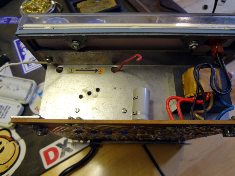
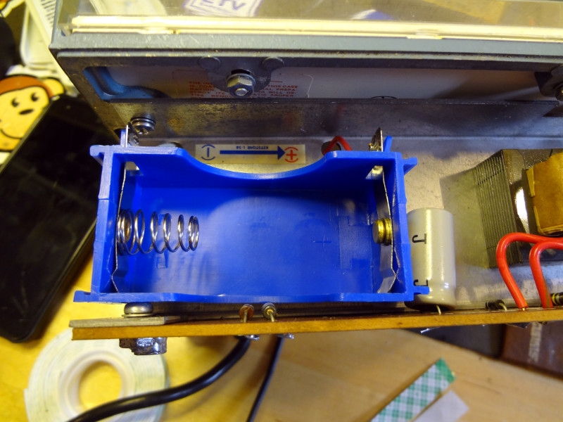
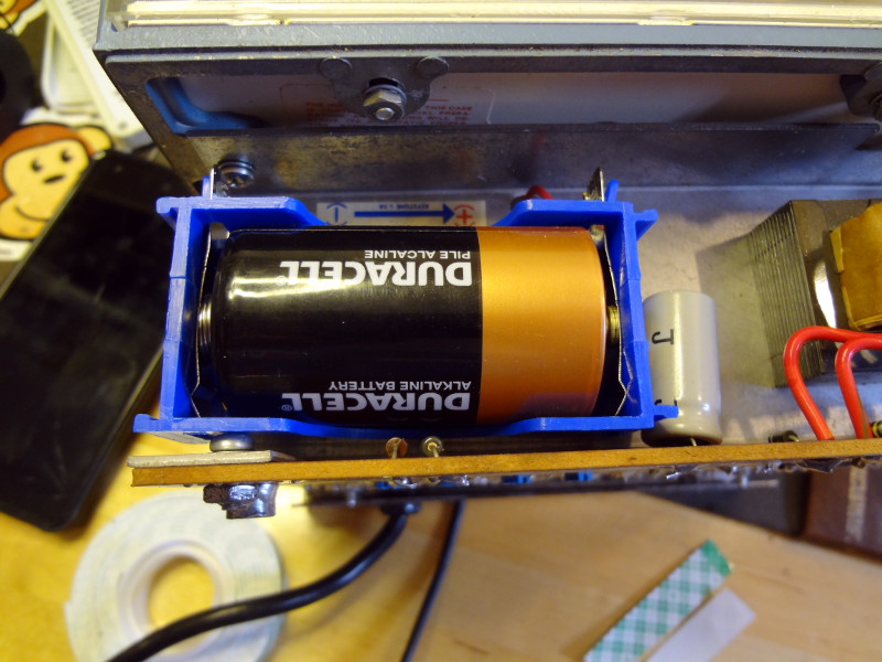
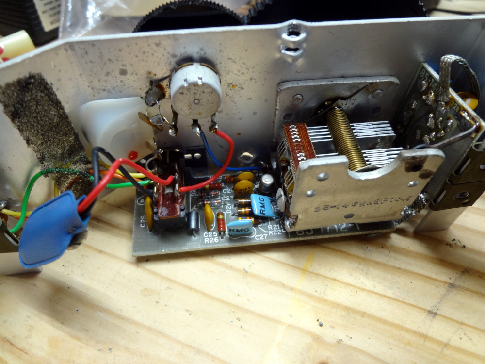
The insides look in pretty good shape, aside from a leaky battery that also took the battery connector with it (easy enough to replace). A few more pieces of disintegrating foam that were originally to cushion the battery, but it was just dry and crumbly fortunately.
Scraping the goo off the face plate was easier once it was freed. Pretty much all of the paint on the top of the face plate ended up coming off. Some of the paint along the top of the side pieces where the foam stuck also had to be scraped off.
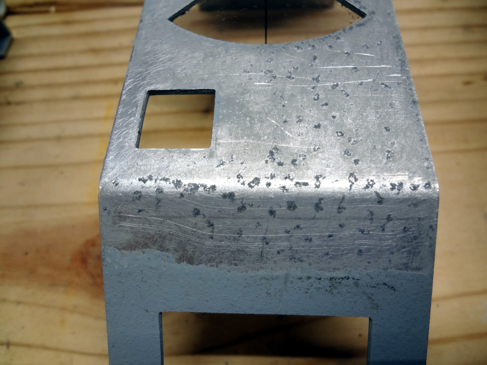
Goo and paint scraped off 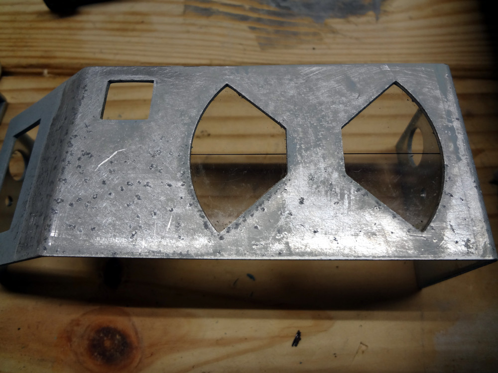
Goo and paint scraped off
There was also a good bit of pitting in the lower part of the face plate from the goo.
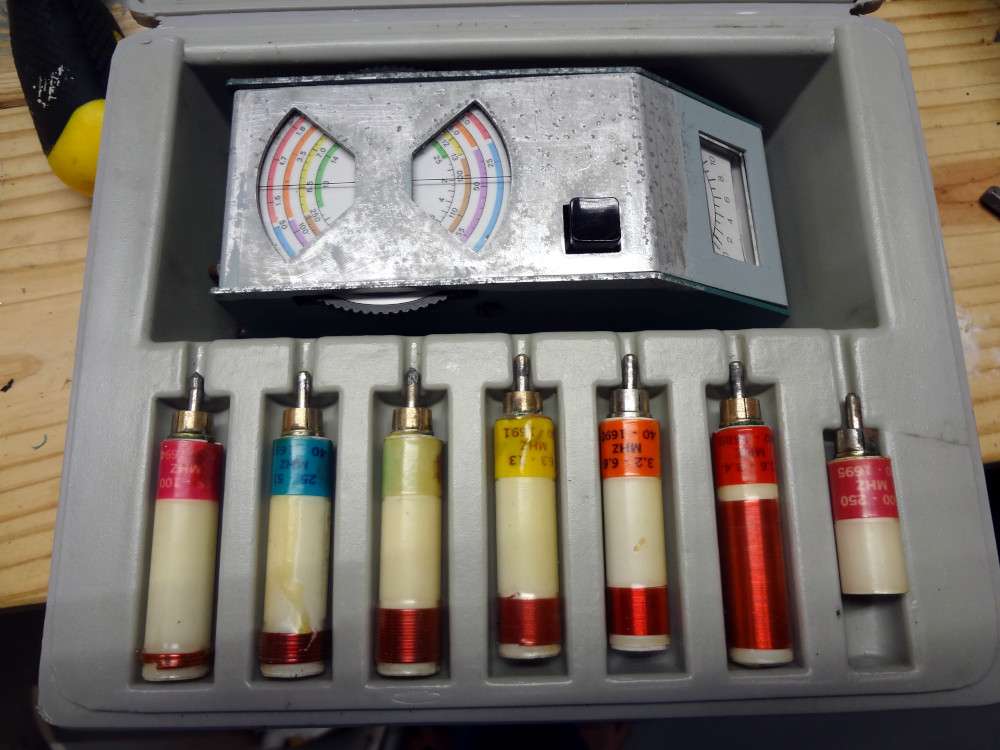
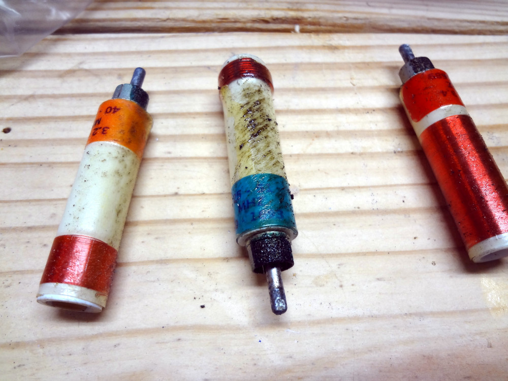
The HD-1250 is a little more bare, but mostly cleaned up. The labels on a couple of the coils have faded away, so there’s no indication of what frequency range they’re for. I’ll have to hunt down a manual and see if the coils are described in it. Aside from some surface corrosion on part of the RCA plug shell (easily sanded off), the coils still look in good shape. The electrical repairs and testing will have to wait for another day.