Etherkit EtherKeyer Mini printed circuit boardKM4CFT 3D printed CW paddlesKM4CFT 3D printed CW paddles
I’ll need to see if I’ve got a spare TRS cord lying around to use with the paddle.
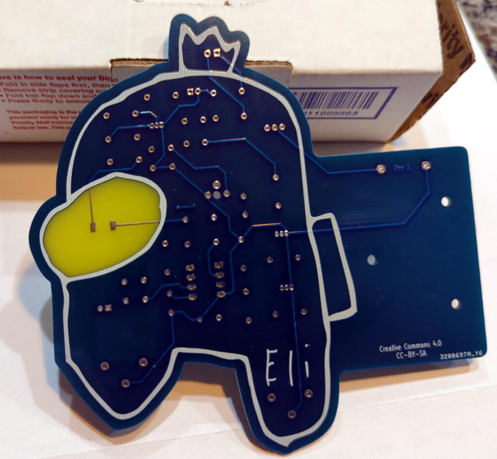
The other board he sent along was a code practice oscillator board (the Etherkit CPO Among Us edition).
Printed circuit board in the shape of a character from the video game Among UsPrinted circuit board in the shape of a character from the video game Among Us
These should make for a fun weekend project.
Jason’s got some fun looking things in the works these days. Go see what he’s been up to on his Applied Etherics Substack.
The Digilent AD2 is pretty cool. The software lets you use the AD2 as an oscilloscope, signal generator, spectrum analyzer, and several other things.
Using the spectrum analyzer function made it pretty easy to set the IG-102 to a frequency, see what the actual frequency was, and then tweak the variable inductor coil for each band setting to tune the output to the dial setting.
All the coils got tuned a bit and now it's calibrated reasonably accurately. Output signal is only around 130 mV (peak), which seems pretty low to me. pic.twitter.com/Ql4YreW0Ee
The output of the IG-102 is pretty low though, less then 0.3 V peak-to-peak. I’m not sure if it’s supposed to be that low, but I expected it would be in the 3-5V range.
Well, at least it outputs something that’s reasonably well calibrated now. I suppose if I had to, I could build an amplifier to feed the signal into. I’ll see if there’s anything else I can do to get the signal amplitude up to where it seems like it should be. Maybe the IG-102 needs the tubes replaced as well.
One of the items from the KB1SH collection of parts I bought at Hamcation was an unassembled frequency counter kit. A packing slip still in the box showed it was purchased from a company called S&S Engineering out of Maryland in 1993. A quick search on Google didn’t yield anything that looked like it might have been related, so the S&S Engineering that produced this kit probably isn’t around anymore.
I love assembling and soldering a good kit, and this looked like a pretty good one. Documentation included the assembly instructions as well as a circuit schematic and a brief theory of operation section. This particular kit included an option for an additional 4 digit LCD display. All the necessary parts turned out to be there, except for a TO-92 voltage regulator that could very well be buried in my carpet somewhere. I neglected to get any photos of the boxed kit, but I did remember to take photos while I was soldering parts on.
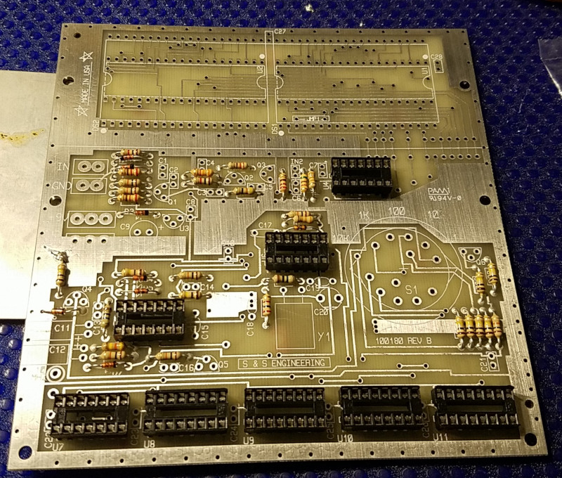
The circuit board for the counter is relatively large, 13.1×13.5 cm and the part density wasn’t high so there’s plenty of room to work on the board while soldering things on. The printed circuit board itself is etched and tinned, but without a solder mask that you’d normally see. The only problem I ran into while soldering were two parts that went into a very large ground plane/heat sink. This would have been a good point to break out the flux and switch to a larger tip on the soldering iron had I thought about it.
Partially assembled frequency counter kit from S&S Engineering
There are a total of 10 ICs in the kit, which I decided to use sockets for. 8 of the sockets and all the resistors are installed in the photo above. The other two were for the 40 pin ICs used to support the LCD displays at the top of the board.
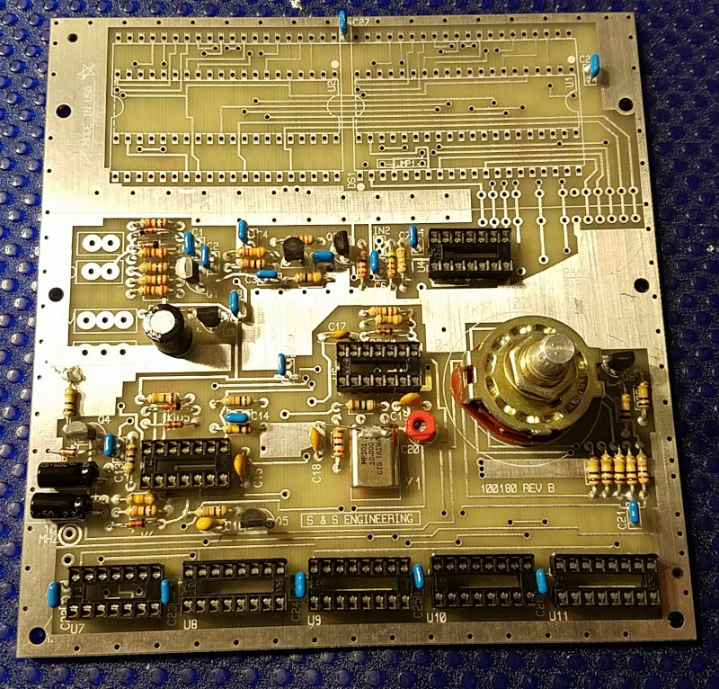
Partially assembled frequency counter kit from S&S Engineering
Above is the fully populated board, except for the two LCD driver ICs and the LCDs themselves.
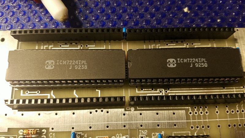
LCD driver ICs installed on the PCB with header pins for the LCD displays
The kit came with two 40 pin sockets, which the instructions say to cut apart and use for the LCD displays. I opted to use the sockets for the ICs, and some tall header sockets for the LCDs.
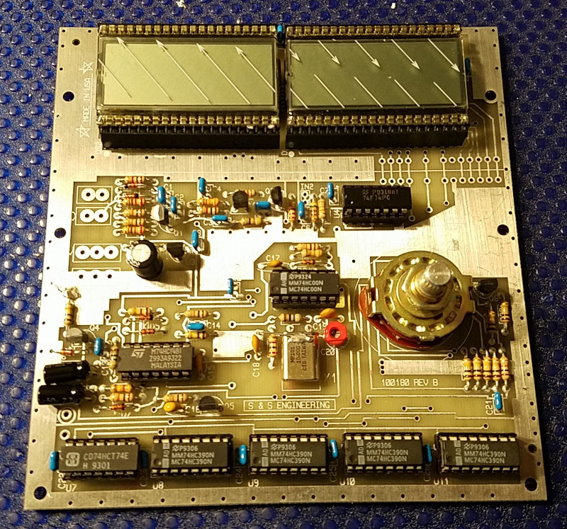
Assembled frequency counter kit from S&S Engineering
The fully assembled board looks pretty nice. Unfortunately, the frequency counter isn’t working yet. I’ve confirmed that the 10 MHz test point puts out something close to a 10 MHz signal, according to one of my DMMs. Not sure if I’ve put in something wrong, bad soldering, or if there’s just a problem with the LCD displays.
Random LCD segments showing up with power applied
A few seemingly random LCD segments show up and then eventually fade after a few minutes. This makes me think it might be an issue with the LCD displays themselves. They are almost 30 years old (at least) after all. I’ll see if I can stick them into a breadboard or something and test them out. Wonder if it would be possible to wire in some other kind of display.
Figuring out how to get this frequency counter working will be as much fun as putting it together I think.
Update: Getting closer to figuring out the problem. Turned out I had the LCD driver ICs installed upside down. I wasn’t paying close enough attention to the installation instructions. With the ICs installed properly (glad I had them in sockets), now I can get the digits to display properly if I wiggle the LCDs in the header sockets to get them into a certain position. I might need to replace the header sockets with something else.
One of my biggest purchases at Hamcation 2022 was a large set of bins and boxes of electronic components from the Swaps building. They were all part of the workbench of KB1SH (SK), and his wife and daughter (very nice people) were at Hamcation with a bunch of his homebrewed radios, tools, and components. I learned from them that KB1SH was an electrical engineer, an avid electronics homebrewer, and spent some time consulting for Ten-Tec. From the radios he built that were on the table, I could tell that he was quite a skilled builder and liked to build with vacuum tubes.
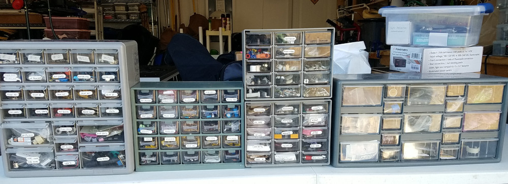
Here are 5 of the 6 component bins I acquired. They’re filled with resistors, capacitors, inductors, transistors, toroids and coils, crystals, connectors, and other bits of hardware for building.
5 of 6 component bins from Hamcation 2022
In addition to the component bins were several boxes of more bagged resistors, caps, inductors, coils, kits of assorted potentiometers and capacitors, tubes of integrated circuits, and spools of wire.
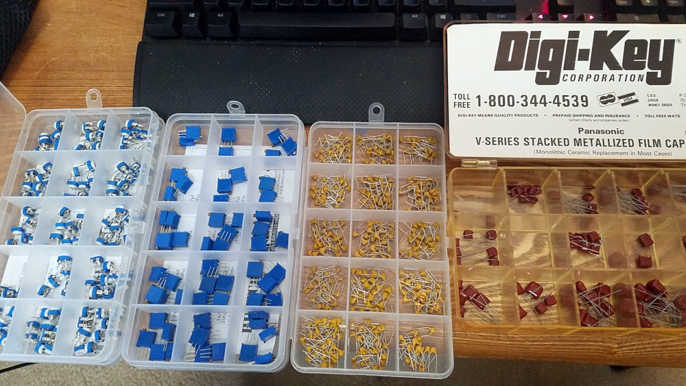
Kits of assorted potentiometers and capacitors. Check out that old school Digi-Key logo!
It’s a pretty vast collection of parts and much of it is new or (now) new-old-stock/NOS. There’s pretty much everything you might need to build something radio-related in the collection.
I still consider myself a bit of a dabbler when it comes to building electronics, but I think KB1SH’s wife and daughter were pleased to know that his collection was going to someone interested in building like he was.
Both books are in pretty good condition, especially the Filter book considering that it was published in 1975. The Antenna Theory textbook still has the 3.5″ disk in the back unopened.
I was hoping to get at least one of the Vibroplex bugs that were also in the auction, but a flurry of last minute bidding drove the price higher than I wanted to pay for them. Oh well.
Happy with the books I managed to get though. They’ll be good additions to the library.