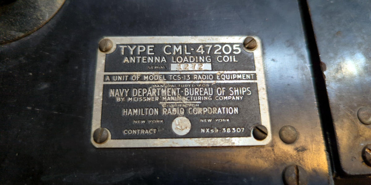
While doing a bit of clean up in the garage, I came across the CML-47205 antenna loading coil units. They came as part of a couple of US Navy TCS-13 transmitter/receivers that ended up in my collection a few years ago.
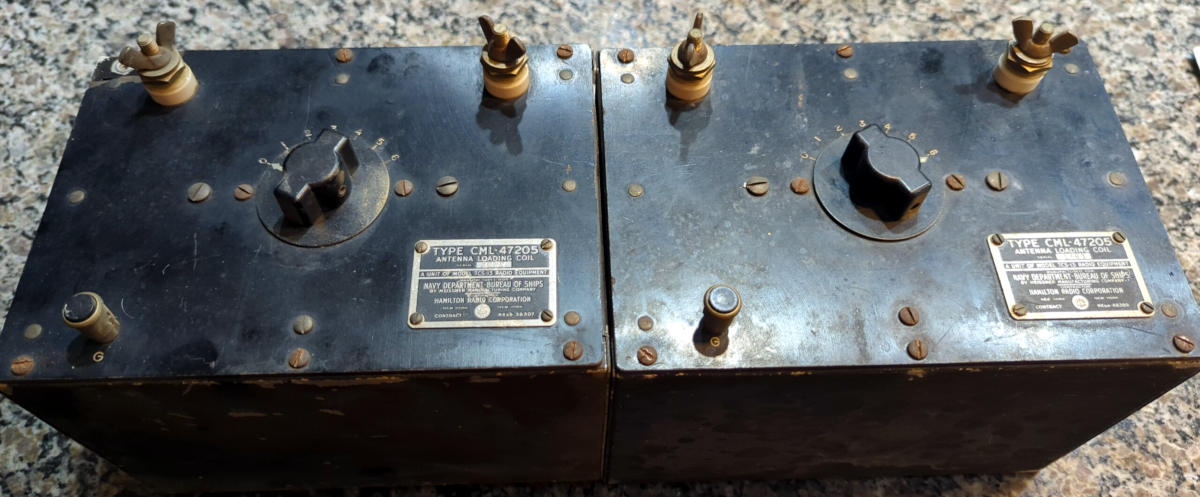
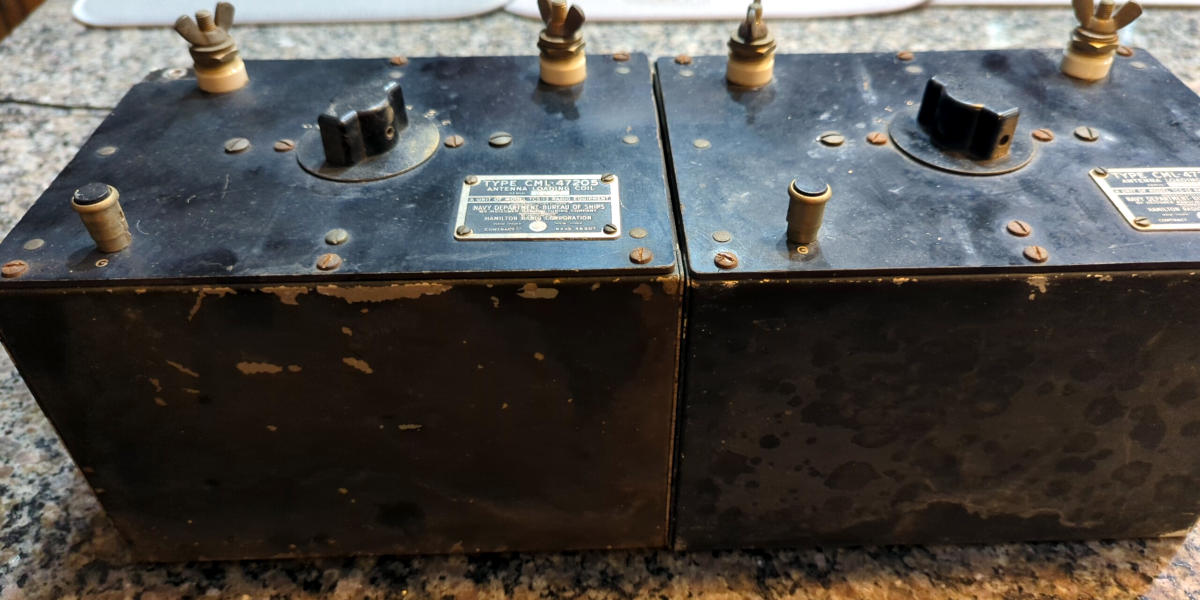
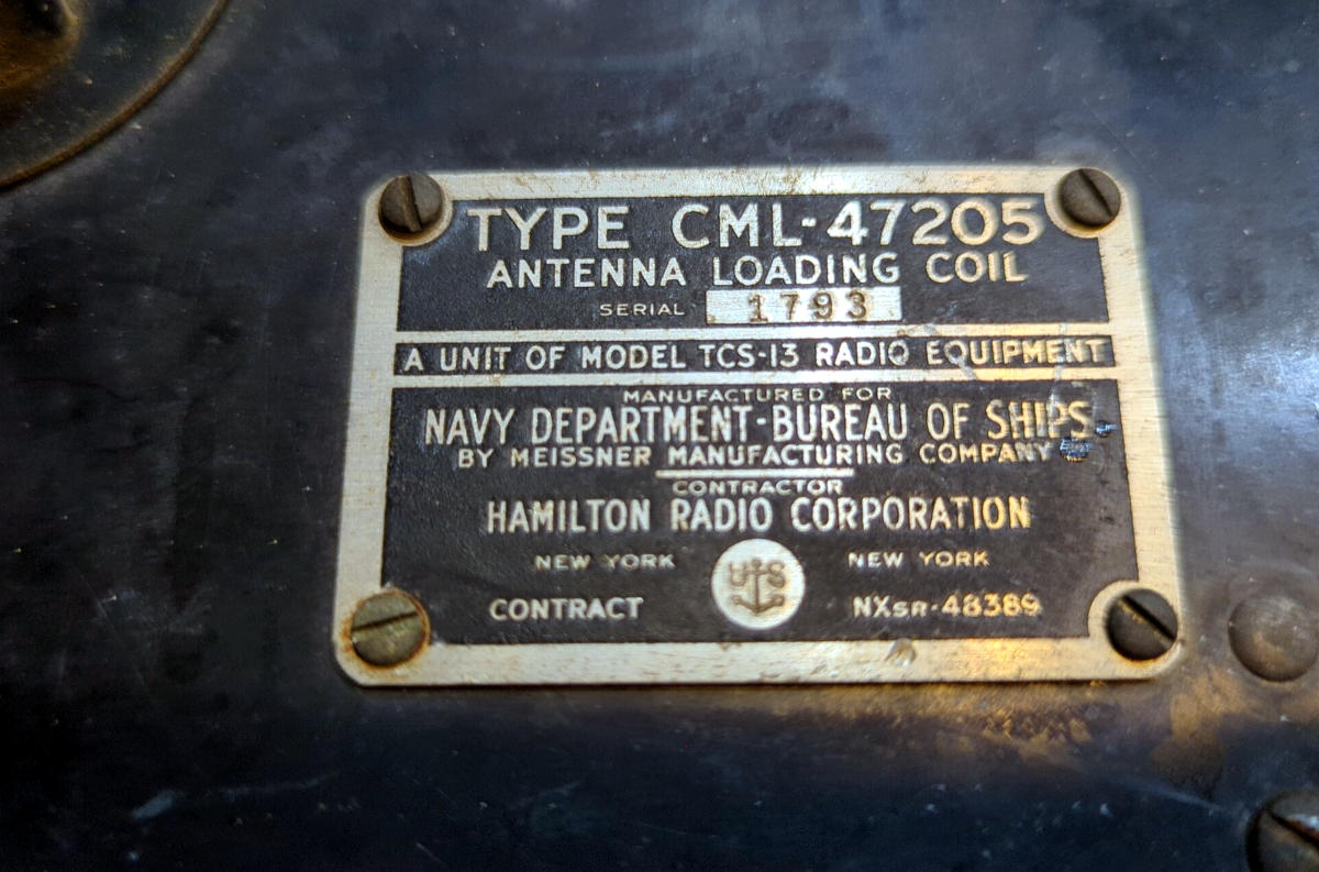
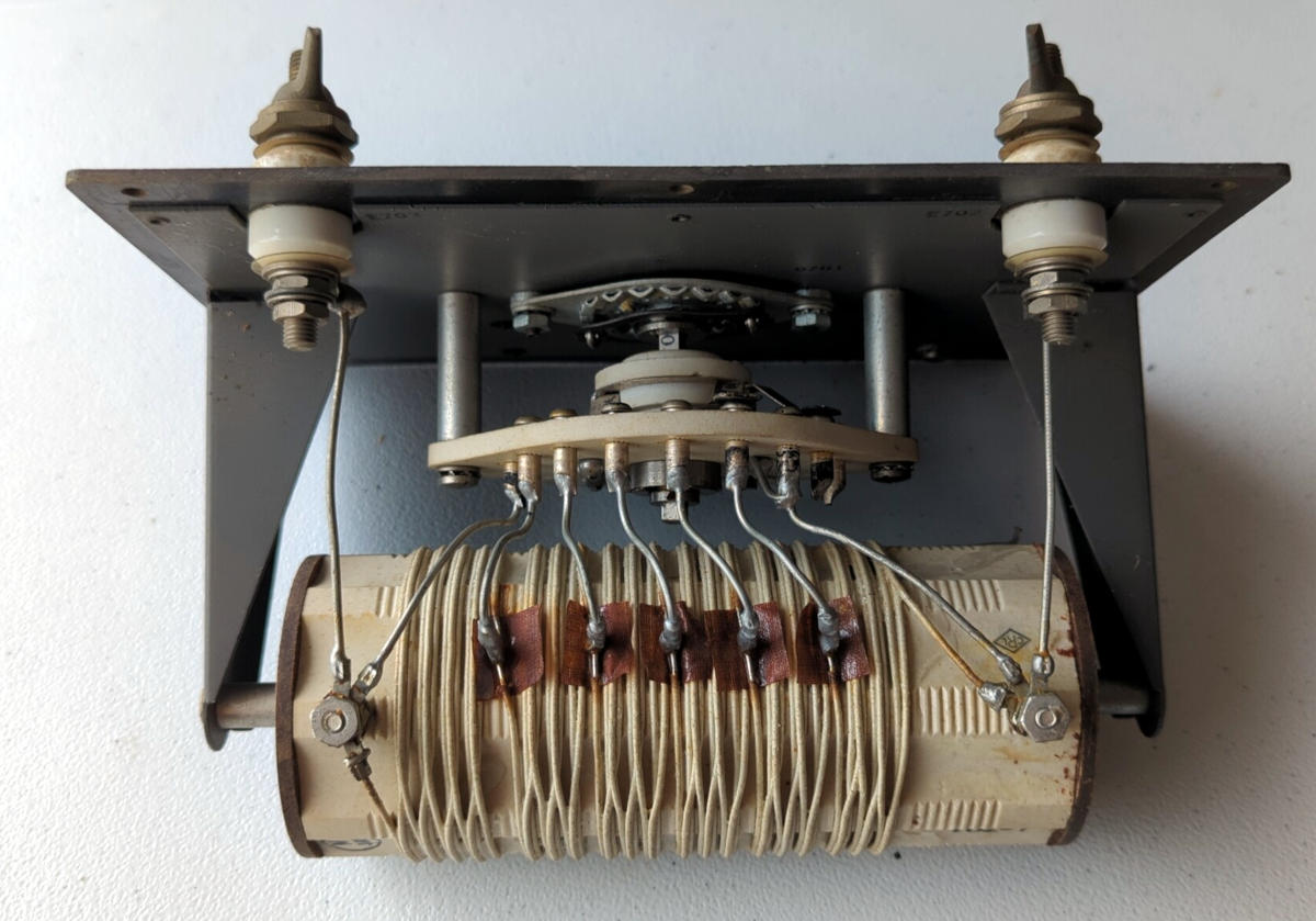
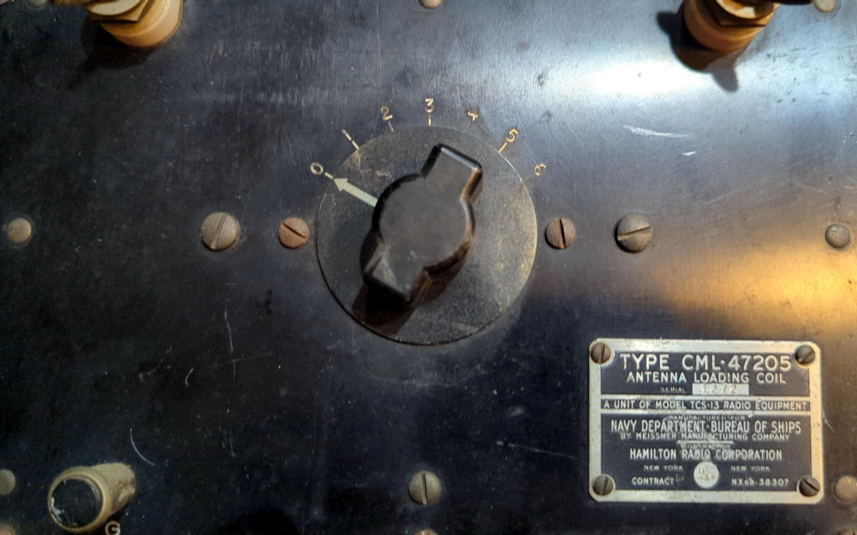
They’re simple black boxes, 6 x 8.5 x 5.75 inches with a 7 position dial switch numbered 0-6, 2 thumbscrew terminals and a ground terminal. The top cover plate appears to be a plastic/resin material (Bakelite or something similar I’m guessing) and the rest of the enclosure is metal. The corner of the top plate on one of the units was broken and the screw missing. Inside it’s pretty simple, a multiposition switch and a tapped inductor coil on a plastic form.
From the manual, it’s meant to be used with a 20 foot whip between 1.5 – 3 MHz. Dial setting 0 selects the highest inductance for the lower frequencies, while dial setting 6 selects the lowest inductance for the higher frequencies.
Using my AADE LC meter connected across the two terminals, I measured the inductance for each position.
| Dial setting | Inductance (μH) SN 1272 | Inductance (μH) SN 1793 |
| 0 | 98.32 | 97.76 |
| 1 | 76.49 | 75.81 |
| 2 | 59.08 | 58.57 |
| 3 | 41.78 | 41.51 |
| 4 | 25.83 | 25.53 |
| 5 | 12.98 | 12.72 |
| 6 | 0.46 | 0.38 |
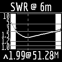
Might be interesting to see if I can incorporate these into a vertical antenna for Field Day.