Diving into the oscilloscope

With the power supply repaired, the next item to go on the bench is the dead oscilloscope.

Hitachi V-1060 oscilloscope

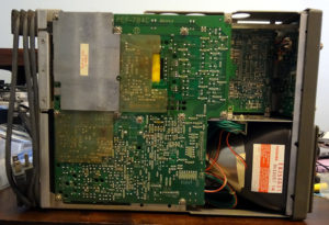
Undoing four screws on the sides of the scope let me slide the top cover off to reveal the innards.

Under the cover
Under the cover
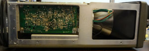
Side view
Side view

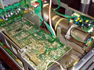
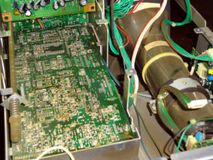
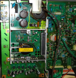
The top circuit board looks to be the power supply board, and probably a few other things. Undoing a bunch of screws holding the top board down and a bit of fiddling around (discovered the board is on a hinge) let me lift it up to reveal more of the scope’s innards.

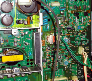
Beneath the power supply board
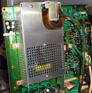
Power supply
Power supply

Three screws hold the cover of the power supply section.

Power supply
Power supply
Power supply
Power supply

A few dust bunnies inside, but overall everything looked to be in fairly decent condition (aside from not working).

First look around the inside didn’t reveal anything obviously wrong. No blown caps or scorched areas.  Whether this is something I’ll be able to repair or not is still up in the air. This scope is probably going to be spending a while on the bench.
Power supply: Fixed!

Yay, the power supply is fixed!

Thomas/LA3PNA suggested I look at the input and reference voltages going into the μA723 regulator, so while I was at it I looked at all the pins in the empty socket. The only unusual thing I found was about 0.1V where the output pin of the regulator went. I’m guessing the voltage regulator probably didn’t like having that much voltage on its output pin, and that’s probably what was killing them.

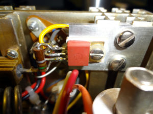
Pin 10 went to the anonymous red transistor type thing, which in turn was connected to the pass transistors and Vcc.

Mystery transistor
Mystery transistor

Consulting with Thomas again, he said it was probably a Darlington transistor or something similar that failed. The μA723 output turns on this transistor, which is then able to provide more current to turn on the pass transistors than the μA723 alone would be able to.

Took the transistor thing out and connected the μA723 output to the base of the pass transistors and everything worked! Got a stable 13.7V at the output of the power supply, and I could turn it off and on again without any problems.

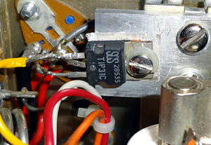
Found a TIP31 power transistor in my collection of parts and put that in place of the dead red transistor and it looks like this power supply is back in business.

TIP31 replacement transistor

It’s a pretty ugly soldering job, but I think it will hold up. Still need to test it  under a load though.

Power supply: Still dead

That power supply that I thought was working again after replacing the fuse? Yeah, not so much. I turned it on again a few days later and the ammeter instantly went up to 27A while the output voltage was only around 2V.

Spent some time poking around some more, but it’s been sitting on the table since then. Last week I ordered some μA723 voltage regulators to fix someone’s Astron RS-35M power supply. Since I had a few extras (ordered 10 of them), I popped one into this dead power supply. Fortunately it’s socketed, so replacing it was pretty easy.

Plugged the power supply in, turned it on and much to my surprise, the power supply seemed to be working again! 13.7V at the output and seemed pretty stable.

Thinking everything was good again, I turned the power supply off and unplugged it, put the cover back on, plugged it back in and turned it back on.

Poof, back up to 27A and no voltage.

Well crap.

Went back in, put in a new μA723, turned it on and it was back to 13.7V. Left it running for a few minutes, turned the power supply off, turned it back on a few minutes later and it was back to 27A and no voltage.

Well double crap. So it looks like there is a deeper issue with the power supply that’s causing it to kill the voltage regulator.

New battery for the Voltohmyst

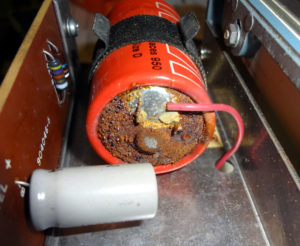
Finally got around to replacing the old corroded soldered-in D cell in the RCA Voltohmyst with a new battery today.

1.5V Battery
1.5V Battery

Snipped the wires off the battery and into the trash it went. Had to drill out a rivet to remove the battery holder clip.

Voltohmyst battery removed

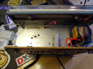
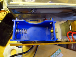
The battery holder is a little on the big side and just fits into the space vacated by the old battery and clip. Soldered the wires onto the battery holder and fastened it to the Voltohmyst using some double sided tape.

New battery holder
New battery holder

Now it’s got a new battery that can be replaced whenever it’s needed.

New battery installed

Next thing to do is go through the  manual and read up on how to calibrate the meter.

A new oscilloscope

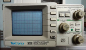
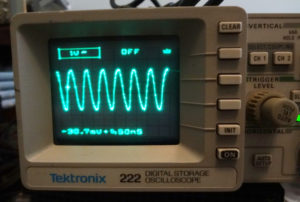
Saw someone at the TARC swap meet with one of these little Tektronix 222 DSOs for sale, so I bought it. Terrific timing since my Hitachi oscilloscope died a while back and I still haven’t gotten around to looking into it.

Tektronix 222 oscilloscope

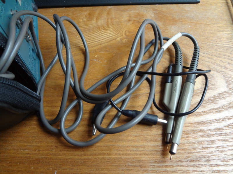
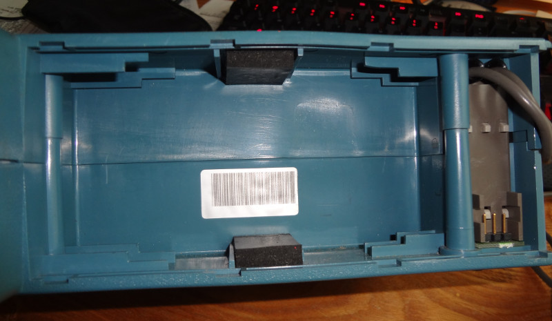
It’s little, and doesn’t have a lot of capabilities but I think it will do pretty much everything I need (at the moment). It comes with two scope probes that are permanently attached. It’s designed to be powered with an 8V SLA battery, but it looks like batteries with the right form factor and voltage aren’t readily available anymore. I did find a promising looking battery replacement project though. This one didn’t come with a battery, but a standard sized power jack lets you power it with wall power. It’s even got a RS-232 serial port!

The scope seems simple enough to figure out how to use without a manual, and I was even able to find a service manual online to download.

Here I’ve got one of the channels measuring the output from one of my Etherkit Si5351 breakout boards. I don’t remember what I have my RedBoard making the Si5351 do, but I seem to be getting a pretty good signal out of it.

Tektronix 222 display