One of my acquisitions from today’s TARC swap meet was a variable power supply. The person I bought it from acquired a bunch of these from a school district surplus auction. I’ve been wanting to get a variable power supply for the workbench, so I bought one of them for $20. Seemed like a pretty good deal. Almost grabbed a second one from him.

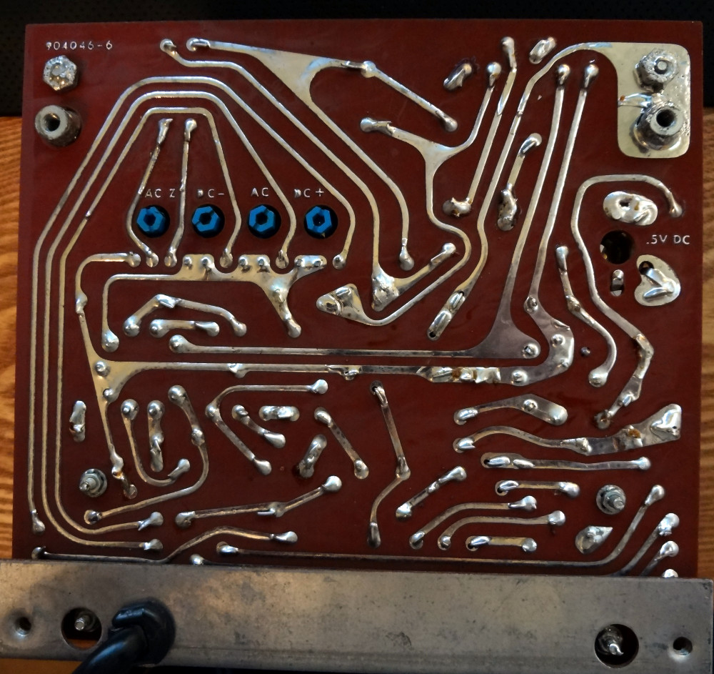
Banana jacks provide AC and DC outputs, and voltage for both is controlled by the knob on the left. Two meters show DC volts and amps, but if you’re using the AC output, you’ll need to measure it yourself.
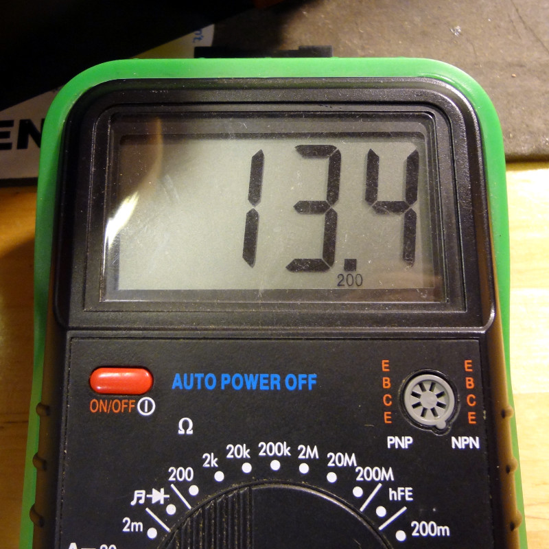
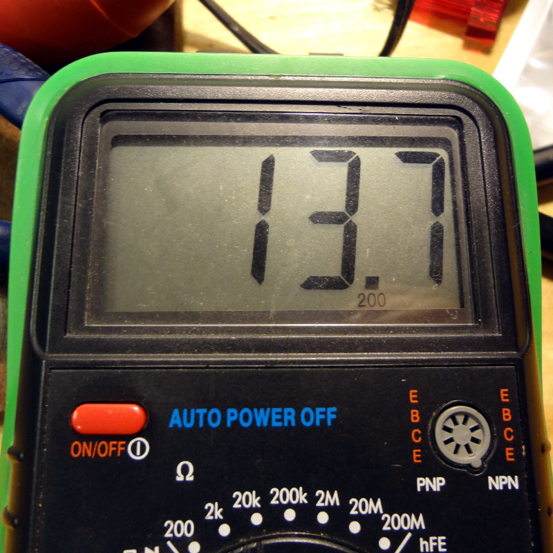
The panel indicates the power supply will do 0-20 VDC and 0-25 VAC. With no load, the power supply topped out at 35 VDC and 26 VAC. This is an unregulated power supply, so any load is going to bring the voltage down.


Getting inside the power supply requires removing a total of 18 screws (6 on each side, 6 on the top). Seems a bit excessive to me, but I didn’t design the thing. Once the screws are out, removing the top exposes the innards.

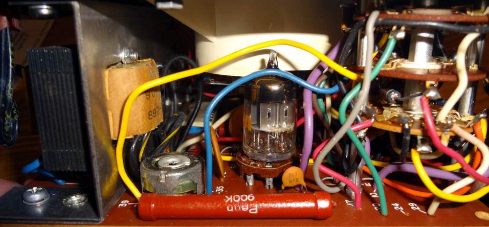
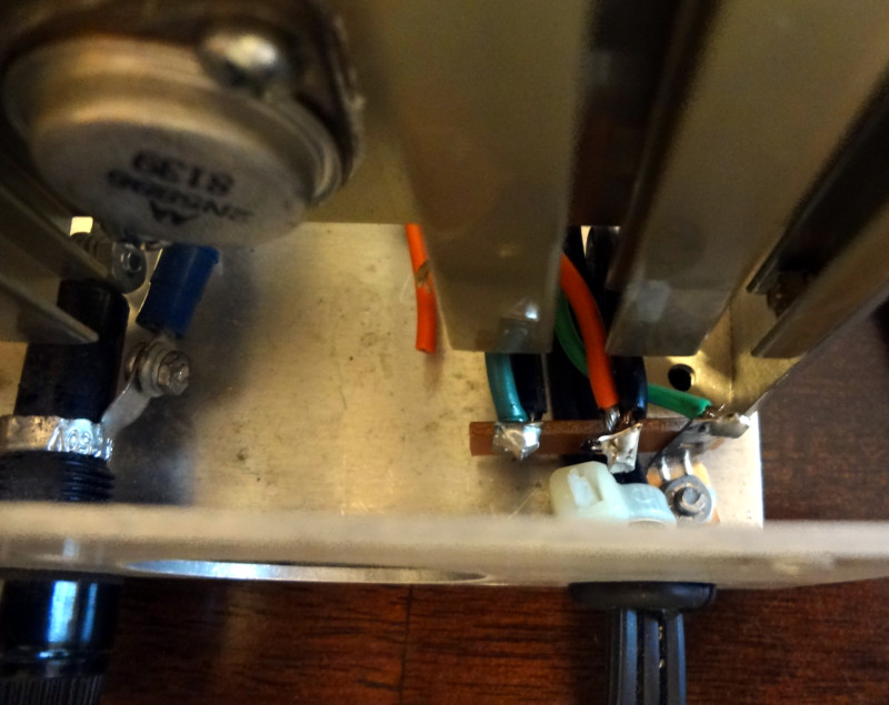
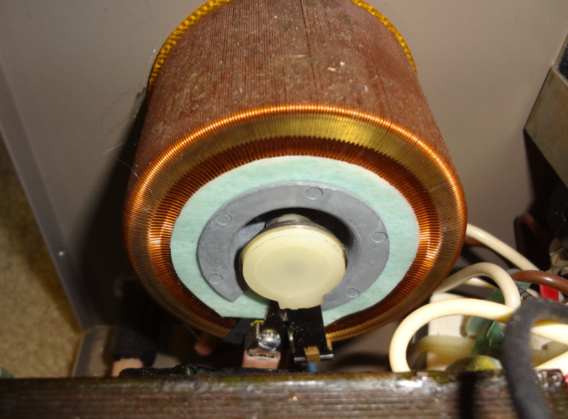
Not much to it inside. There’s a big beefy transformer which accounts for almost all of the power supply’s weight. Voltage control is performed by the variac. A large (and loud) 120mm fan (lower right) provides cooling.


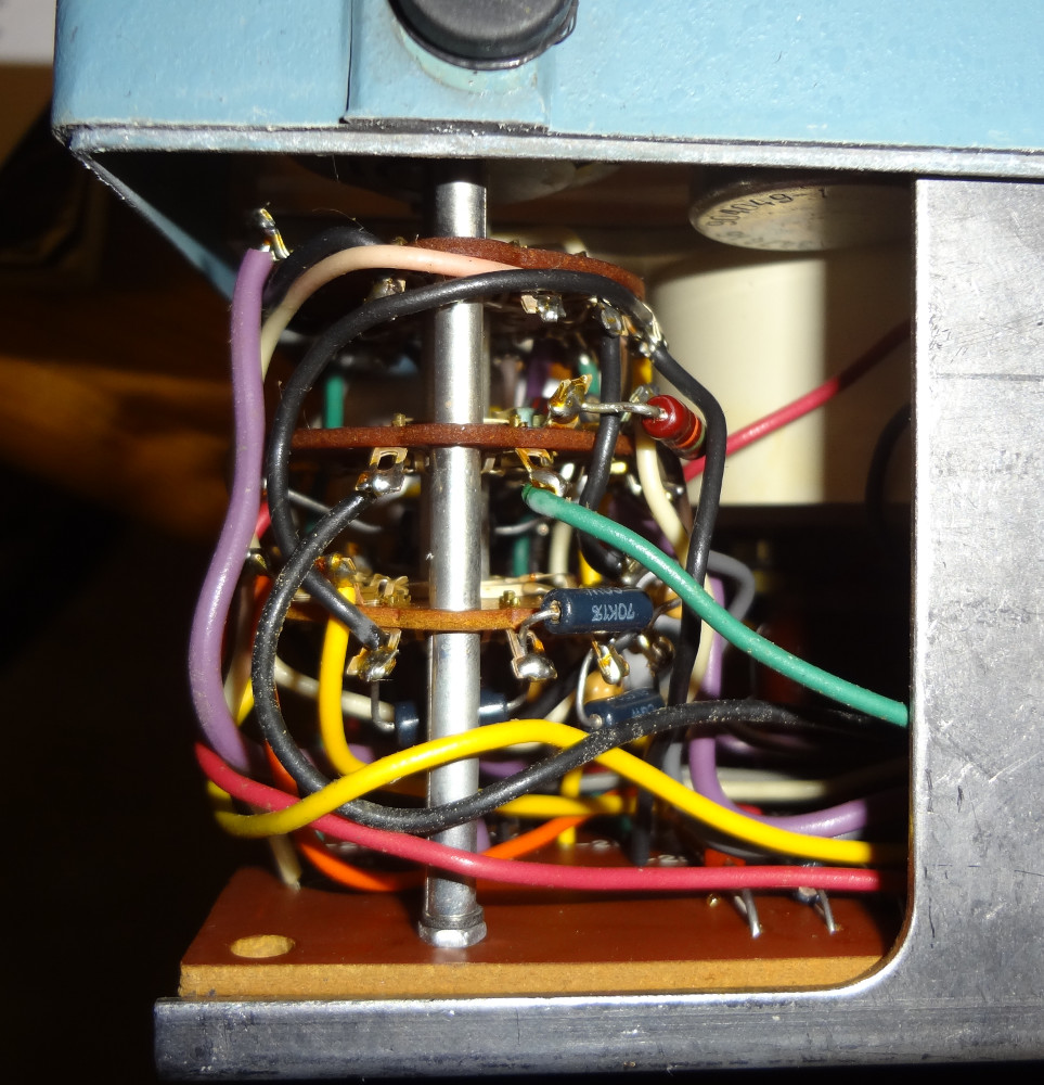
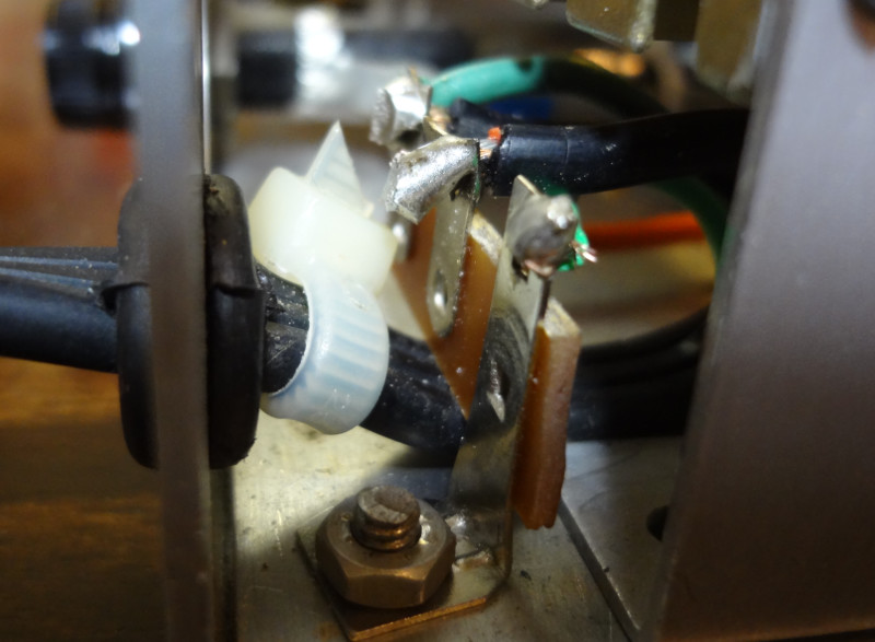
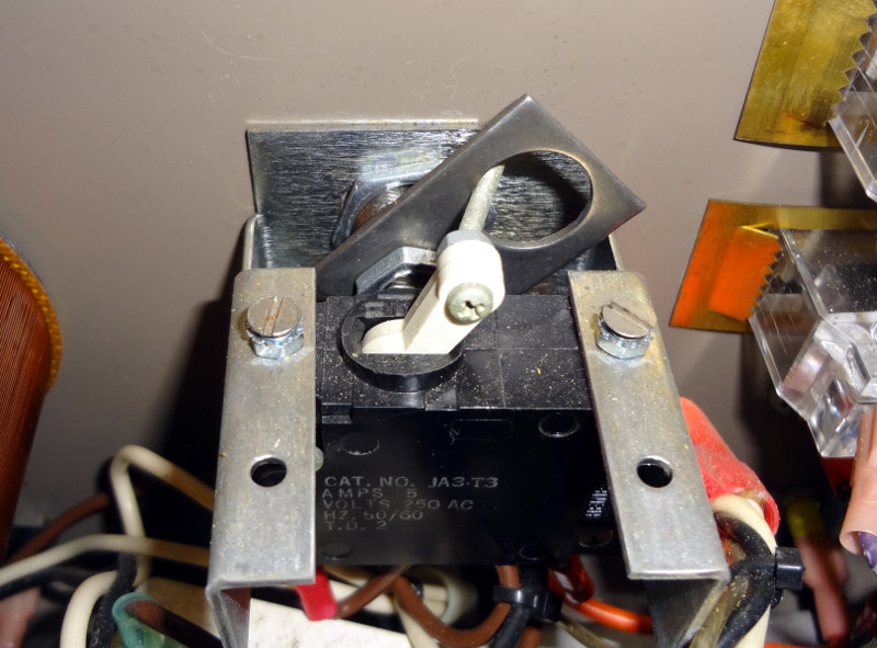
The key just turns a metal plate that flips the actual power switch on or off.
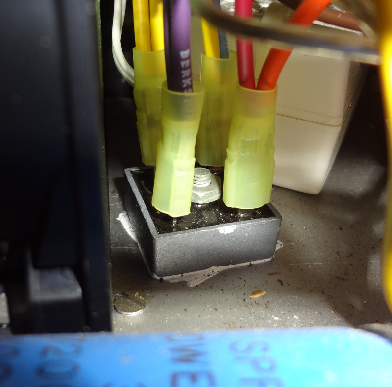
The cooling fan gets its own power supply so that it’s not affected by changing the output voltage. It’s just a 12V wall wart that gets powered from the AC input I think (haven’t traced any of the wires to see what goes where).

Plenty of modification potential with this power supply. I’ve got a small list of easy ones that I think I’ll make:
- Replace the key with a regular switch
- Switch out the banana plugs for 5-way binding posts and Powerpole connectors
- Replace the fan with a quieter one
This seems to be a pretty sturdy power supply designed for the harsh environment of a high school lab. Everything inside looks to be in pretty good condition.