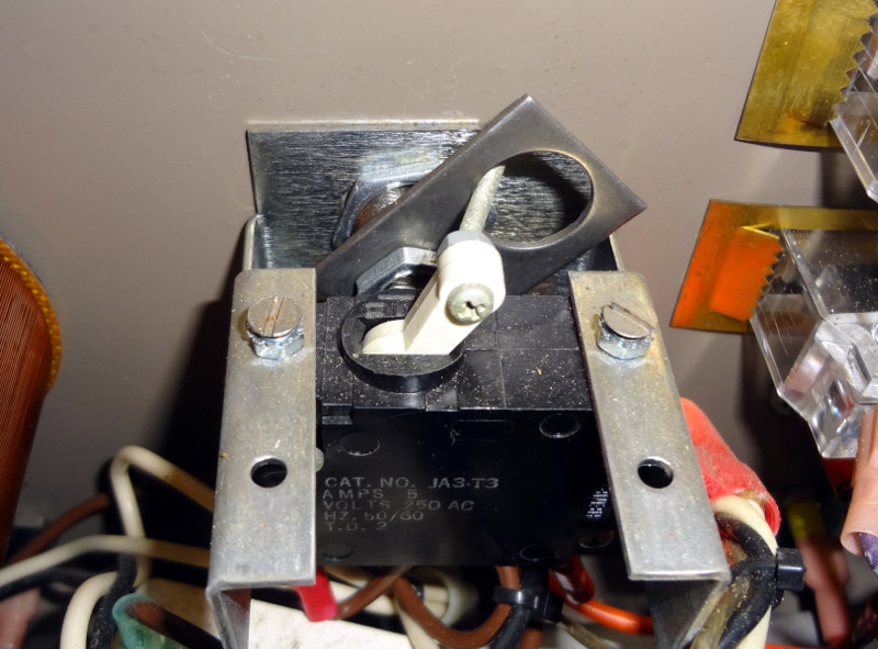
Thomas/LA3PNA suggested I look at the input and reference voltages going into the μA723 regulator, so while I was at it I looked at all the pins in the empty socket. The only unusual thing I found was about 0.1V where the output pin of the regulator went. I’m guessing the voltage regulator probably didn’t like having that much voltage on its output pin, and that’s probably what was killing them.
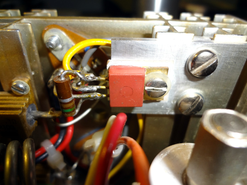
Pin 10 went to the anonymous red transistor type thing, which in turn was connected to the pass transistors and Vcc.
Mystery transistor
Consulting with Thomas again, he said it was probably a Darlington transistor or something similar that failed. The μA723 output turns on this transistor, which is then able to provide more current to turn on the pass transistors than the μA723 alone would be able to.
Took the transistor thing out and connected the μA723 output to the base of the pass transistors and everything worked! Got a stable 13.7V at the output of the power supply, and I could turn it off and on again without any problems.
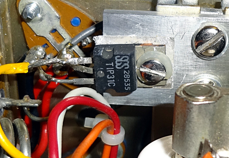
Found a TIP31 power transistor in my collection of parts and put that in place of the dead red transistor and it looks like this power supply is back in business.
TIP31 replacement transistor
It’s a pretty ugly soldering job, but I think it will hold up. Still need to test it under a load though.
That power supply that I thought was working again after replacing the fuse? Yeah, not so much. I turned it on again a few days later and the ammeter instantly went up to 27A while the output voltage was only around 2V.
Spent some time poking around some more, but it’s been sitting on the table since then. Last week I ordered some μA723 voltage regulators to fix someone’s Astron RS-35M power supply. Since I had a few extras (ordered 10 of them), I popped one into this dead power supply. Fortunately it’s socketed, so replacing it was pretty easy.
Plugged the power supply in, turned it on and much to my surprise, the power supply seemed to be working again! 13.7V at the output and seemed pretty stable.
Thinking everything was good again, I turned the power supply off and unplugged it, put the cover back on, plugged it back in and turned it back on.
Poof, back up to 27A and no voltage.
Well crap.
Went back in, put in a new μA723, turned it on and it was back to 13.7V. Left it running for a few minutes, turned the power supply off, turned it back on a few minutes later and it was back to 27A and no voltage.
Well double crap. So it looks like there is a deeper issue with the power supply that’s causing it to kill the voltage regulator.
One of my acquisitions from today’s TARC swap meet was a variable power supply. The person I bought it from acquired a bunch of these from a school district surplus auction. I’ve been wanting to get a variable power supply for the workbench, so I bought one of them for $20. Seemed like a pretty good deal. Almost grabbed a second one from him.
Variable power supply
Banana jacks provide AC and DC outputs, and voltage for both is controlled by the knob on the left. Two meters show DC volts and amps, but if you’re using the AC output, you’ll need to measure it yourself.
The panel indicates the power supply will do 0-20 VDC and 0-25 VAC. With no load, the power supply topped out at 35 VDC and 26 VAC. This is an unregulated power supply, so any load is going to bring the voltage down.
Max 35VDC unloaded
Max 26VAC unloaded
Getting inside the power supply requires removing a total of 18 screws (6 on each side, 6 on the top). Seems a bit excessive to me, but I didn’t design the thing. Once the screws are out, removing the top exposes the innards.
Power supply innards
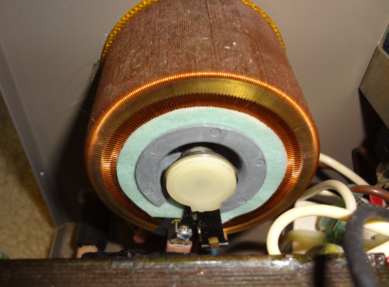
Not much to it inside. There’s a big beefy transformer which accounts for almost all of the power supply’s weight. Voltage control is performed by the variac. A large (and loud) 120mm fan (lower right) provides cooling.
Variac autotransformerBack of the voltage and current metersFull wave bridge rectifierBig filter capacitorCooling fan
The key just turns a metal plate that flips the actual power switch on or off.
Power switch
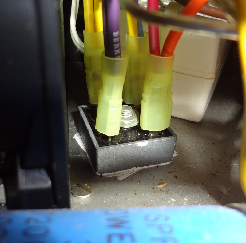
The cooling fan gets its own power supply so that it’s not affected by changing the output voltage. It’s just a 12V wall wart that gets powered from the AC input I think (haven’t traced any of the wires to see what goes where).
Cooling fan power supply
Plenty of modification potential with this power supply. I’ve got a small list of easy ones that I think I’ll make:
Replace the key with a regular switch
Switch out the banana plugs for 5-way binding posts and Powerpole connectors
Replace the fan with a quieter one
This seems to be a pretty sturdy power supply designed for the harsh environment of a high school lab. Everything inside looks to be in pretty good condition.
Off I went to the last remaining Radio Shack in my area (a franchise store, also known as Hurricane Electronics) to see if I could find some fuses and a replacement lamp. Found some replacement fuses easily enough (35V, 20A), and much to my surprise, replacement bulbs that were the exact same style as what was already on the power supply.
Replacing the light was easy enough, but took a bit longer than expected. The original pair of wires for the light kept breaking when I tried to put the light back into place, so I ended up just replacing the two wires with some 18 gauge stranded wire I had. Once the light was back in place, I plugged the power supply in and on came the light. Yay!
Power supply light
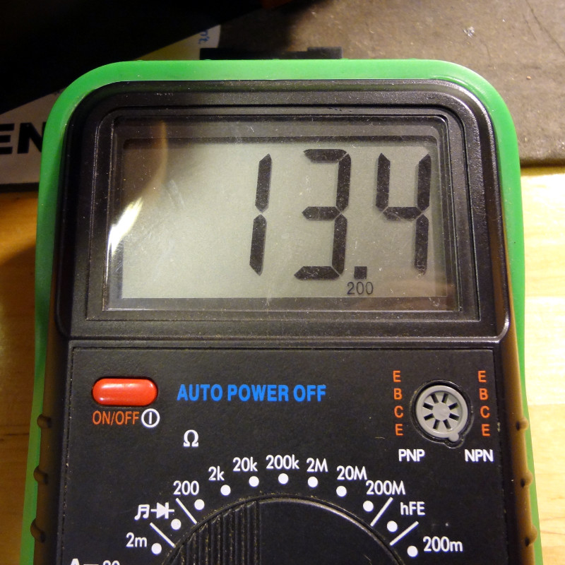
Then I replaced the fuse, turned it back on and was greeted with the meter telling me there was 13ish volts. With my DMM, I read 13.3 V DC at the meter.
13.4V DC output
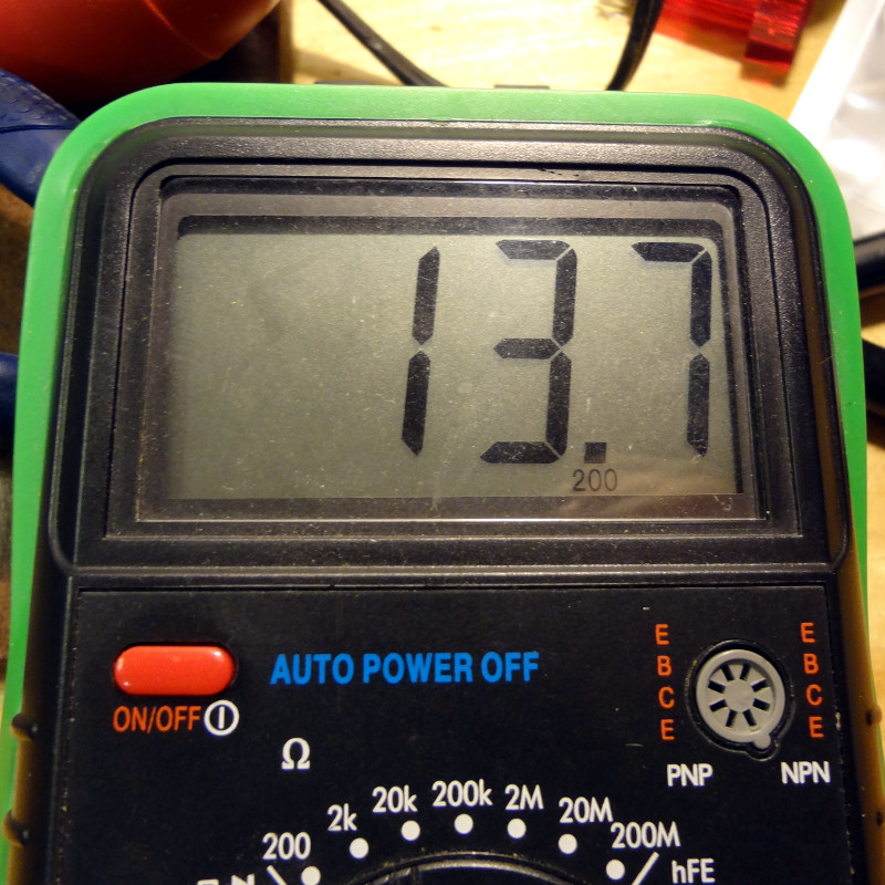
I tweaked the pot at the control board to bring it up to 13.7 V DC.
Tweaked up to 13.7V DC output
So it looks like the only problem with the power supply was the blown fuse. Now to see how it works with a load applied.