Spent another evening poking around inside the Heathkit IG-102 signal generator, this time with schematic in hand and probing around with my DMM to check voltages in various places. I wanted to make sure everything was working ok, and it seems to be. The voltages I was getting were all pretty close (within 10%) of what was printed on the schematic.
I also replaced the original 60s or 70s era power cord with a polarized power cord (harvested from I don’t remember what now). It was a simple replacement and probably not critical but I figured having a new(-ish) cord might make it a little more electrically safe. The hard part was unsoldering the old cord and getting the plastic strain relief thing out of the chassis.
I was able to set my HT to a few frequencies in the 10-30 MHz range and heard tones when I adjusted the signal generator to those frequencies. That seems like a good sign it’s working.
Spent some time poking around inside my Astron PS with a schematic in hand. It was interesting having another look inside and examining things a little closer.
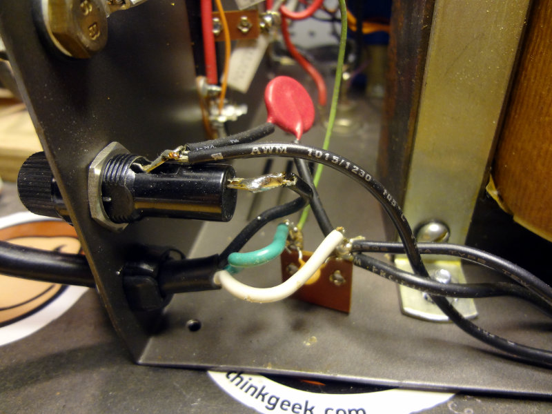
With the schematic, I was able to identify a few components that I didn’t immediately recognize. At the AC input side, I found a varistor, VR1, (150L10) in between the fuse and the switch, rather than between the switch and the transformer as shown on the schematic. None of the schematics I see show it like that so it makes me wonder if the PS has had some “work” done to it.
Astron RS-35A power input
Here’s the wiring on the AC input side
Astron RS-35A power input
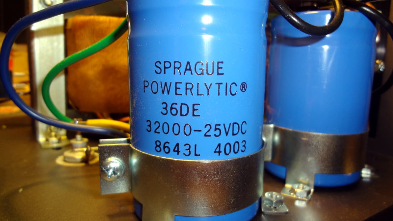
The schematic shows a 64 mF 25V electrolytic capactor (C5) filtering the output of the transformer, but in my unit that was accomplished with two large 32 mF capacitors in parallel. Probably easier that way. A 64 mF capacitor would be pretty big.
Power filtering caps
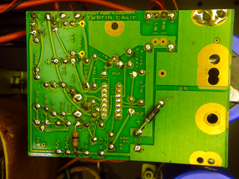
Output from the transformer goes into the control board which handles regulating the output of the power supply.
Power regulation board
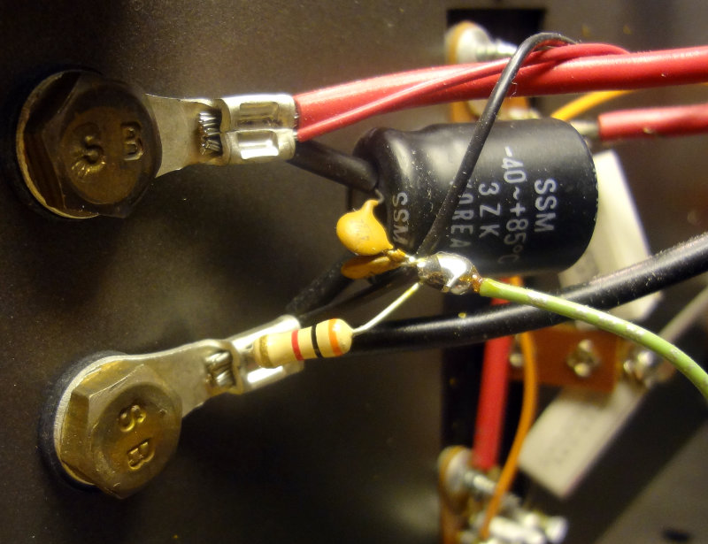
The 2N3771 pass transistors are easily seen on the back of the power supply where the heatsink takes up pretty much the whole rear panel. On the inside 0.05 Ω 5W power resistors hang off them.
2N3771 pass transistors
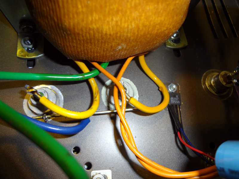
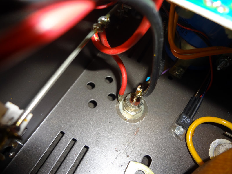
The high current output of the transformer goes into a couple of 1N1184A power diodes that appear to be set up to do simple half wave rectification. Schematics in later models show a pair of bridge rectifiers doing full wave rectification on the transformer output. The newer models probably produce a lot less ripple in the output waveform than mine does. My power supply has the 1N1184A diodes (CR101 and CR102) bolted to the chassis. The thick yellow wires feed the diodes and the thinner orange wires go to the control board. The green wire is a center tap off the transformer and goes to the negative terminal of one of the 32mF capacitors.
1N1184A power diodes
Also bolted to the chassis is a TIP29A transistor (Q2) using the chassis as a heat sink. Later models have this on the control board with a small heat sink.
Another diode looking thing is bolted to the chassis, which according to the schematic is a S0535H diode (SCR1). I can’t confirm this using the text stamped on it though.
S0535H SCR diode
This leads to the output of the power supply, which has a 2200 μF capacitor (C101) across the output terminals. Where the schematic shows just a single 10 nF capacitor also across the output terminals, mine has what appears to be two 47 nF capacitors (some older schematics show them as 10 nF caps) each connecting one terminal of the 2200 μF capacitor to ground, along with a 3000 Ω resistor from the negative terminal to ground. This is something that I saw on earlier schematics, but not on later ones. Apparently they’re for filtering out sags or spikes if the load on the output changes.
I’ve been pondering some modifications to make to my Astron power supply. The first mod I considered was replacing the nut/bolt terminals with Anderson power pole connectors, but it looks like that will require replacing some wiring and what appears to be additional filtering components which I think I’d rather not do in case I mess things up. Plus I’d also have to square out the round holes for the power pole terminals. I think I’ll just make up some pigtails with power pole connectors instead.
I think it would also be neat to have a volt and current meter on the PS to monitor the output. There’s plenty of room on the front panel of the PS for meters, but my metal working tools and skills are limited and I’m not sure I’d be able to do a proper job yet. I think the easiest way for me to add the meters is make a separate enclosure or panel for them that will sit on top of the PS. That should be easy enough to do.
One interesting thing that I noted while browsing the Astron part of the Repeater Builder site is that all of the schematics for the RS-35M/RS-35A they have show only one large 2.2 mF filtering capacitor while there are two in my PS. Don’t know if that’s an addition to newer models, or if it was someone else’s mod.
After taking another look at the first pictures I took, it looks like there may already be a thermistor (the red thing that I think looks like a thermistor anyway) added in the circuit.
Think I’ll open it up again and have a closer look at what’s inside.
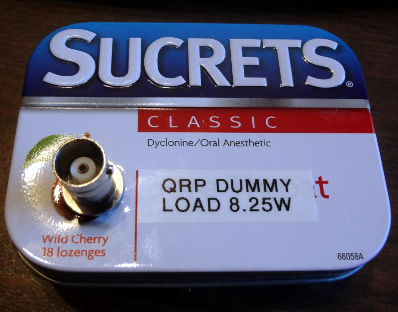
A little Sucrets tin turned out to be a good size for my QRP dummy load.
Dummy load enclosure
Dummy load enclosure
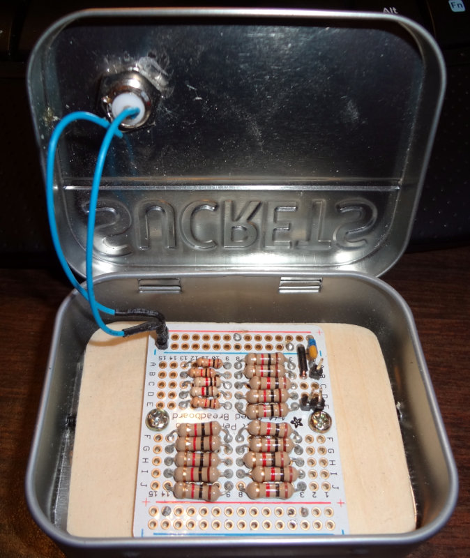
A short section of 1×4 sliced in half to about 1 cm thick serves as the base. The dummy load is screwed onto the board and the board glued into the tin. For extra security, I put three screws through the sides of the tin into the board.
On the antenna analyzer, it reads pretty close to 51Ω and 1.0 SWR between 3-10 MHz. Above that the impedance creeps up to as high as 55 Ω and 1.5 SWR below 28 MHz. SWR shoots up pretty high in the VHF range.
I don’t have an external connection for the power measurement yet. Still need to figure out how I’m going to do that. For now it will be an “open the lid” measurement.
The templates for the faceplates I made worked out pretty well. The holes weren’t perfect, but I blame that on using a drill to make the holes. Would have been much easier if I had a drill press, or ideally a hole punch. For the BNC hole, I didn’t have a 1/4″ drill bit so I just used a 3/8″ bit (the largest I had) and my Dremel with a sanding drum to enlarge the hole.
CC1 enclosure
CC1 enclosure
Looks pretty good in its enclosure I think. Now I need to put some labels on it.