Another ARRL Field Day weekend has come and gone.
This year was a pretty good one. I spent a little less time at the radios this year than in previous years, but it was still busy.
Started out with getting the radio at home set up on battery power (2 SLA batteries that had been pulled out of my UPSs) and getting the antenna mostly up in the air.
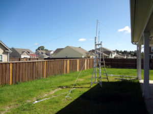
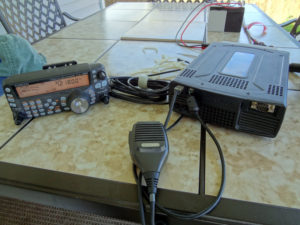
I didn’t get to use the radio at home, but Connie was able to use it to make a contact Saturday evening. She started off at 5 W, but wasn’t able to break any pileups. After stepping up to a few different power levels, she was able to make a contact at 50 W, which the batteries apparently handled without complaint. The antenna setup is far from ideal, and I imagine most of the 50 W she had to use ended up warming up the sky overhead. But it still worked. Operating at reduced power is something we’ll have to work on.
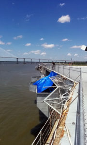
The bulk of my Field Day was spent at the USS Yorktown. Once we got the operating positions set up, it was just a matter of waiting for the festivities to start at 1800UTC. We had our usual operating locations off the port side of the flight deck.
We also had a lot more visitors to our Field Day operation than in past years. The lady in charge of the overnight camping program at Patriots Point brought groups of Scouts and other campers by every now and then, so we got to show them a little bit about what amateur radio was about.
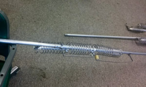
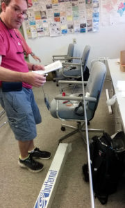
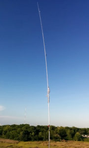
Our digital station was set up on a dipole mounted on the starboard side of the flight deck but it wasn’t performing very well, so it ended up getting replaced by a Butternut multi-band vertical that was stashed away in the club room. After some assembly, we got the dipole down and the vertical up and everything was performing beautifully.
One of the things that makes doing Field Day from the Yorktown so great is the view. It’s pretty hard to beat.


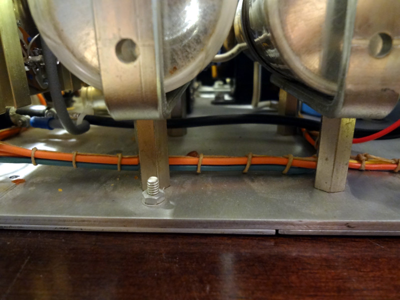
Sunday morning, the alternate power source was pulled out of the club room and put to work.
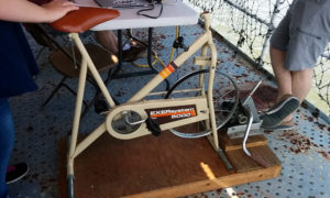
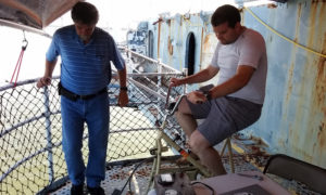
It’s an old exercise bicycle with an alternator attached to the front wheel via a belt. It actually works well enough to power a radio. Unfortunately, the load on the alternator when the radio transmits makes you feel like you’ve suddenly hit a wall while pedaling and the radio shuts off because you’ve stopped pedaling. Entertaining, but not very effective.
Overall, another excellent and fun Field Day with CARS/WA4USN. I think next year I’ll try to do a bit more of Field Day from home.