Replacing the DC blocking disc capacitor (C20, 0.01 μF) just before the Fine Atten pot helped clean up the output signal quite a bit. I didn’t get a picture of the wave form before, but it was pretty ugly looking and not very stable.
IG-102 wave form, about 500 kHz
Much better looking now, and much more stable.
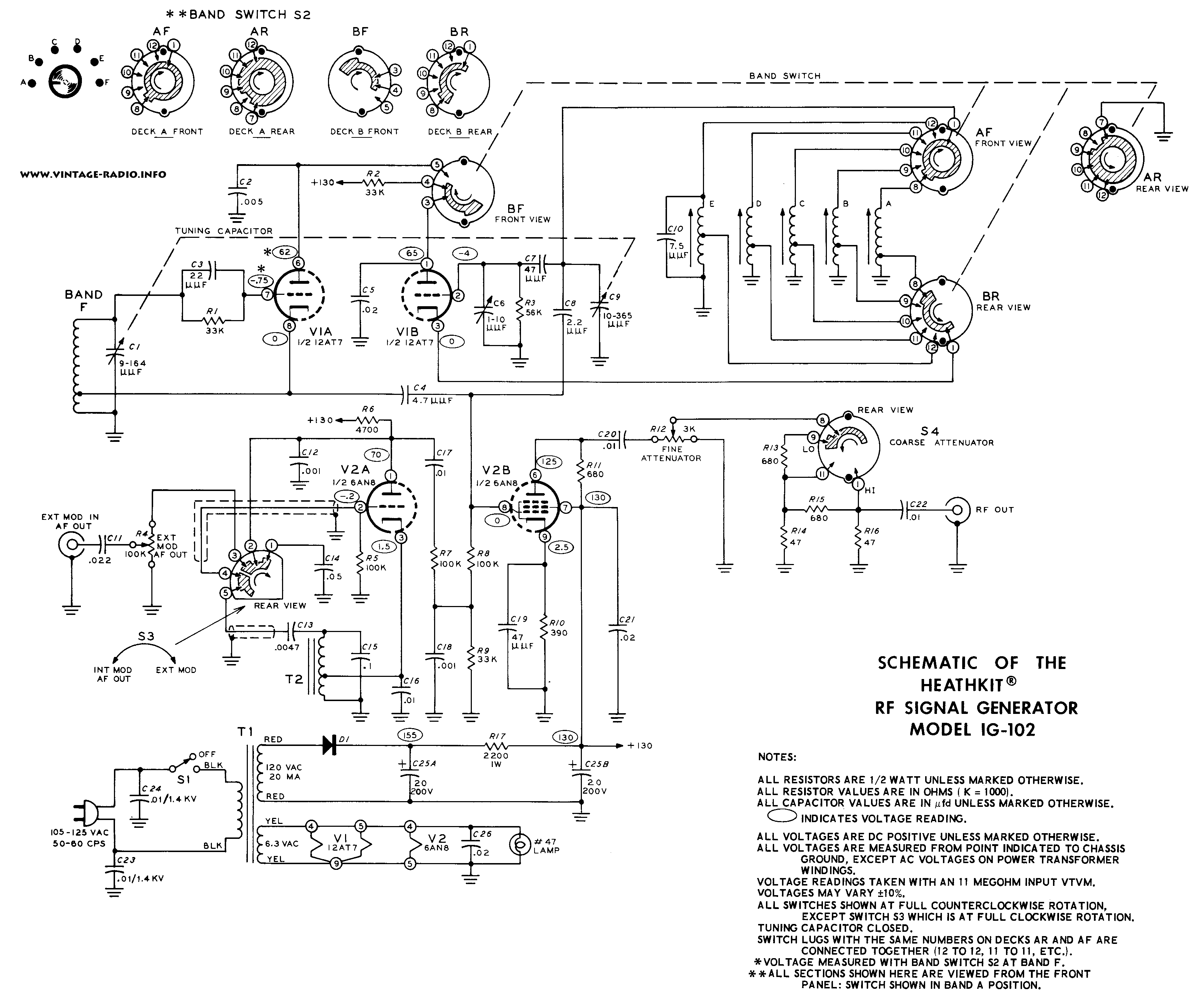
Heathkit IG-102 schematic from https://www.vintage-radio.info/
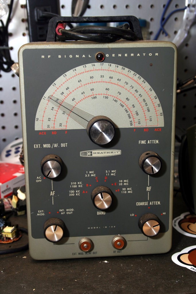
Fortunately, my IG-102 came with the assembly manual. The IG-102 is roomy enough inside that it’s pretty easy to get in and probe around checking things.
Things I’ve found so far:
Audio frequency (AF) output, which the manual says should be 400 Hz, is around 260 Hz. With the AF dial turned all the way up, the AF waveform measures about 20Vpp.
I can reliably get RF output when the Coarse Atten switch is at the Hi position and the Fine Atten dial is all the way clockwise.
Setting the Coarse Atten switch from Hi to the middle position drops the frequency by about a factor of 10 (according to my M3 frequency counter).
Setting the Coarse Atten switch to the Lo position makes the RF output drop out.
Turning the Fine Atten dial counter-clockwise ends up changing the frequency (unexpected) instead of changing the signal level.
The band select dial is kind of fiddly. Sometimes when I switch to a different band, RF output drops out. Switching back and forth will usually bring the RF output back.
Band A (100 – 300 kHz) is the most accurate.
Bands B (310 – 1100 kHz) and C (1 MHz – 3.2 MHz) are about 50 kHz low.
Band D (3.1 – 11 MHz) is low by 0.5 – 0.7 MHz.
Band E doesn’t work.
Band F (32 – 110 MHz) is reasonably accurate up to 50 MHz, but maxes out around 75 MHz.
V1 12AT7 pin voltages
Pin
Spec
Measured
1
65
62
2
-4
-5
3
0
0
4
6.3 VAC
7 VAC
5
6.3 VAC
7VAC
6
62
59.6
7
-0.75
-0.38
8
0
0
9
0
0
V2 6AN8 pin voltages
Pin
Spec
Measured
1
70
62.8
2
-0.2
-0.5
3
1.5
1.57
4
6.3 VAC
7 VAC
5
0
0
6
125
127
7
130
130.9
8
0
0
9
2.5
2.64
IG-102 AF signal around 260 Hz
The RF signal sampled at pin 2 of the 12AT7 tube looks decent enough.
IG-102 RF signal around 370-ish kHz
Need to do some more poking around with the oscilloscope to check the RF waveform at other places along the output path to see what’s happening before I try to figure out what bits I might need to replace.
This time, I’ll replace that big orange capacitor with something newer (along with any other components that look like they need replacing). The signal generator doesn’t seem to be putting anything out at the BNC connectors anymore, so that will be another thing I’ll check.
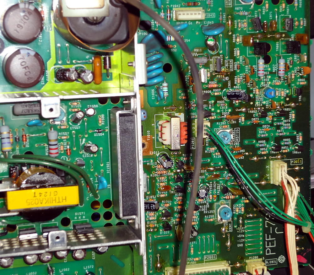
My dead oscilloscope is still dead. After spending some time poking around the innards, I’m starting to think the issue is on the high voltage side that provides power to the CRT. I’ve checked the voltages at connectors where the PCB is labeled with voltages, and those match up. It seems like the rest of the scope is probably working except for the CRT side of things.
I think at the moment, the scope is beyond my ability to fix. Guess I’ll shelve it for now and maybe go back to it when I’ve gained a few more skill levels and higher level items.
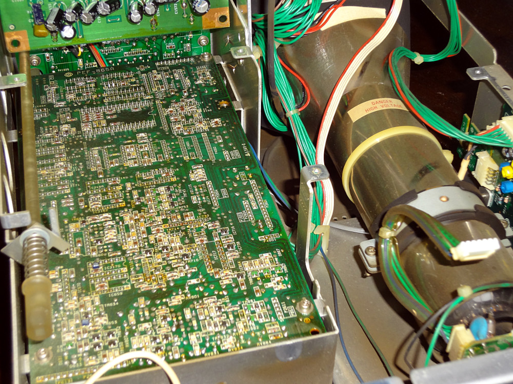
Undoing four screws on the sides of the scope let me slide the top cover off to reveal the innards.
Under the cover
Side view
The top circuit board looks to be the power supply board, and probably a few other things. Undoing a bunch of screws holding the top board down and a bit of fiddling around (discovered the board is on a hinge) let me lift it up to reveal more of the scope’s innards.
Beneath the power supply board
Beneath the power supply board
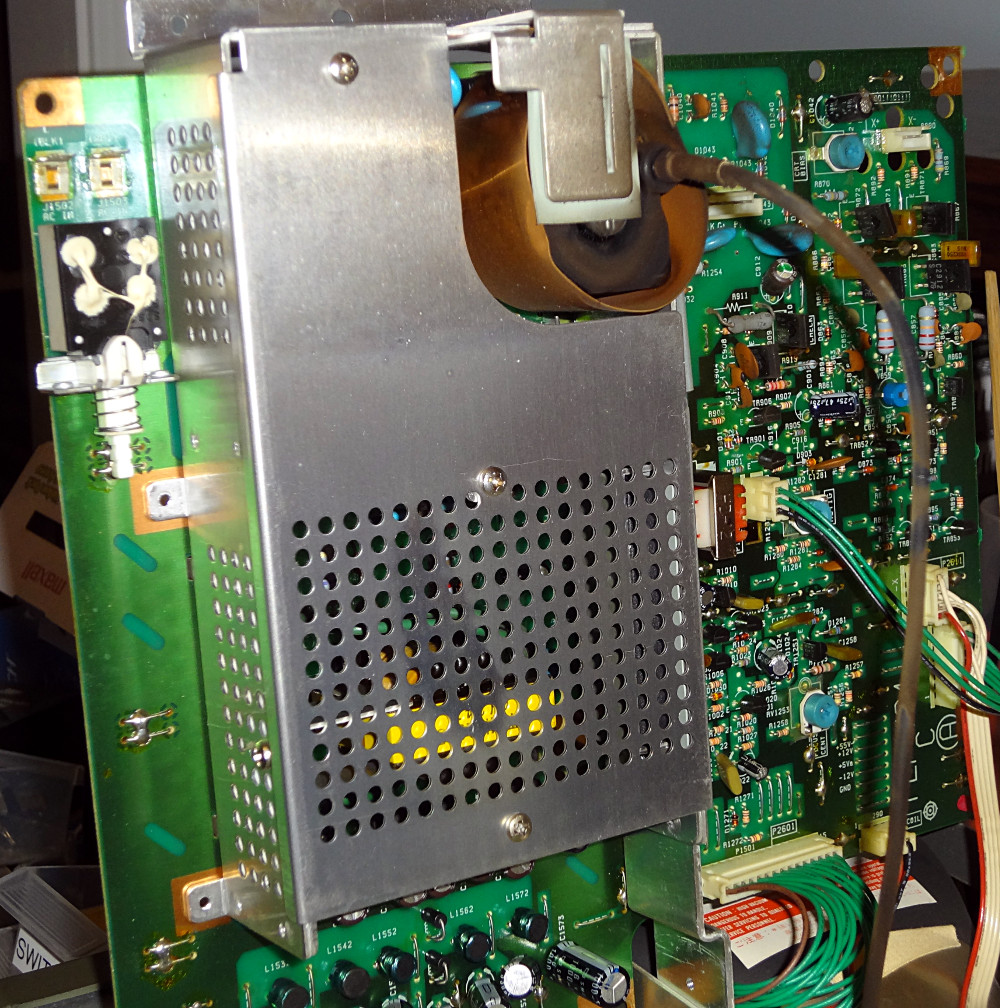
Power supply
Three screws hold the cover of the power supply section.
Power supply
Power supply
A few dust bunnies inside, but overall everything looked to be in fairly decent condition (aside from not working).
First look around the inside didn’t reveal anything obviously wrong. No blown caps or scorched areas. Whether this is something I’ll be able to repair or not is still up in the air. This scope is probably going to be spending a while on the bench.