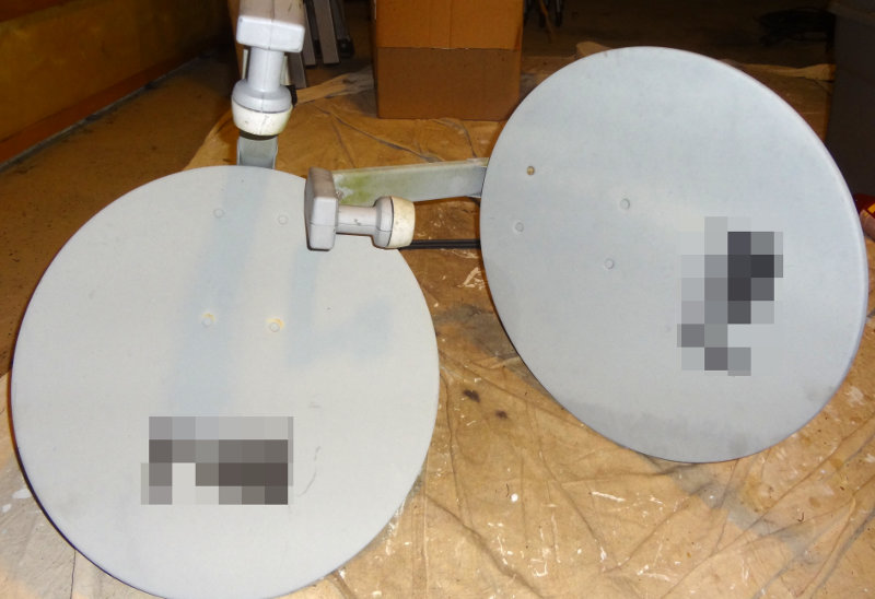
As I pulled into the driveway after work today, I noticed one of the neighbours had placed a couple of satellite dishes by the curb for disposal. First thing to cross my mind was “Hmm, I wonder if I could do something with those…”. Mentioned it to Connie and she said “Grab them” so I did.
Satellite dishes
They also came with a mess of coax (probably 75 Ω stuff) that’s probably been sitting outside for who knows how long, so could be of questionable quality by now. It will give me something to start off working with though.
RG-6 coax
Not entirely sure what I’ll do with them yet. I’ve read in various places on the web about people using them for various simple science experiments/demonstrations, like recording solar radio emissions. It will probably take me a while to even do anything with them. I’ll have to spend some time researching different options and finding out what other people have done with them.
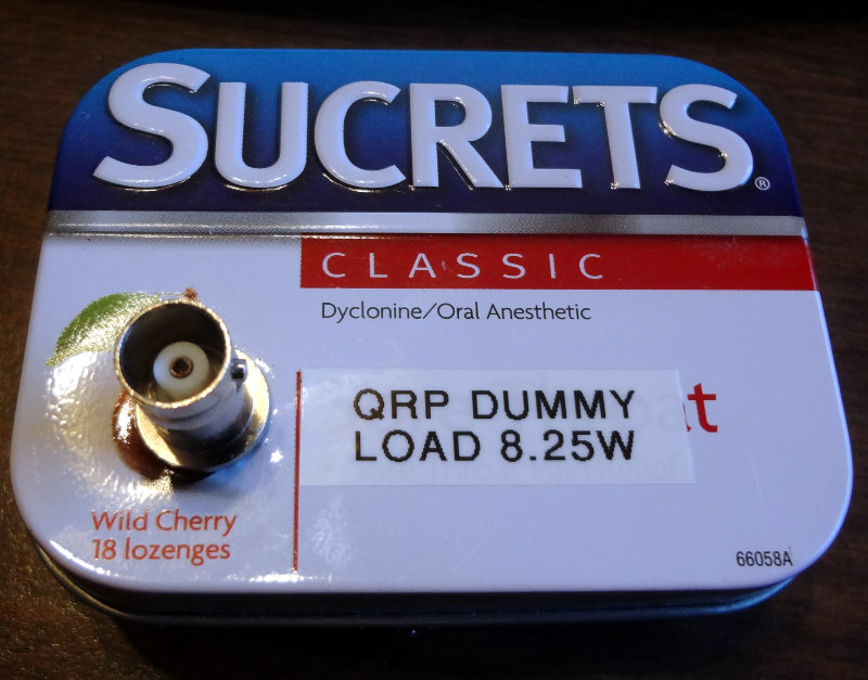
A little Sucrets tin turned out to be a good size for my QRP dummy load.
Dummy load enclosure
Dummy load enclosure
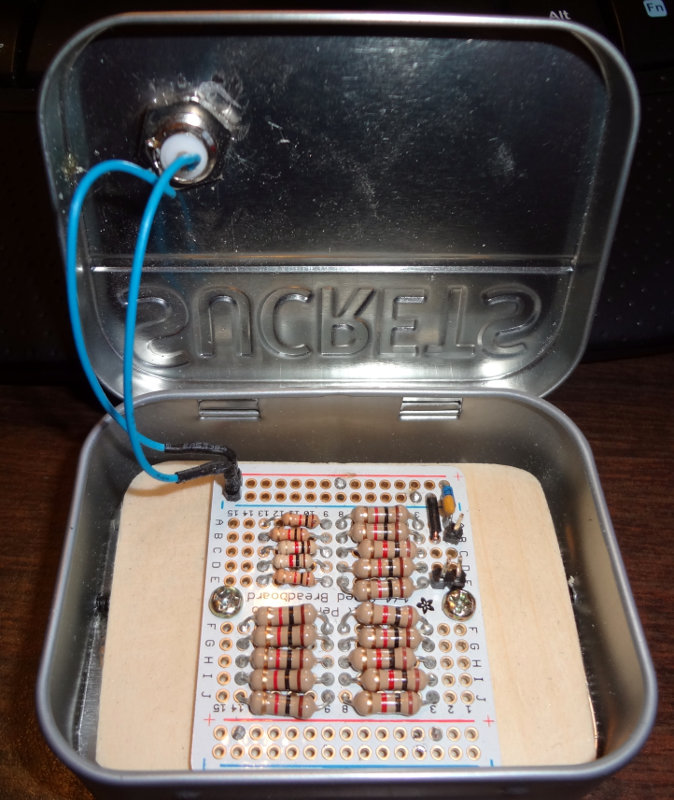
A short section of 1×4 sliced in half to about 1 cm thick serves as the base. The dummy load is screwed onto the board and the board glued into the tin. For extra security, I put three screws through the sides of the tin into the board.
On the antenna analyzer, it reads pretty close to 51Ω and 1.0 SWR between 3-10 MHz. Above that the impedance creeps up to as high as 55 Ω and 1.5 SWR below 28 MHz. SWR shoots up pretty high in the VHF range.
I don’t have an external connection for the power measurement yet. Still need to figure out how I’m going to do that. For now it will be an “open the lid” measurement.
The templates for the faceplates I made worked out pretty well. The holes weren’t perfect, but I blame that on using a drill to make the holes. Would have been much easier if I had a drill press, or ideally a hole punch. For the BNC hole, I didn’t have a 1/4″ drill bit so I just used a 3/8″ bit (the largest I had) and my Dremel with a sanding drum to enlarge the hole.
CC1 enclosure
CC1 enclosure
Looks pretty good in its enclosure I think. Now I need to put some labels on it.
Update: After a couple of iterations with paper, some of the measurements were adjusted and the drawing updated. I’m pretty sure the measurements are accurate and will serve to help other CC1 builders create a drilling template for their build. As always, keep in mind the “measure twice, cut once” principle. YMMV. Links to my templates are at the end of the post. Feel free to use them as a starting point for your CC1 build.
In preparation for drilling out the holes in the face plates for the CC1 enclosure, I used my digital calipers to measure the distances to the center of each of the connectors that would need a hole.
First I started measuring while holding it in my hand, but I realized there’s a little bit of play when the board is in the enclosure and measurements would change depending on how I was holding it.
I decided to place CC1 and enclosure on the table and starting with the left-most connector (A), measure it’s position relative to the left and bottom edges of the enclosure. For the remaining connections, I just measured the offset from the first one since their positions are fixed. Seemed like the most accurate way of doing things.
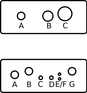
The face plates are 74mm x 29mm. The top one is the back plate with the largest hole corresponding to the BNC jack. The bottom one is for the front plate. The Dia version should be to scale, but when I printed it, it was just a tiny bit short along the x-axis. Apparently printer scaling and computer scaling is a tiny bit different. It should still be pretty close to use as a template though. Will try cutting it the paper version to see how well it fits before I start drilling.
These are the measurements I came up with
Front plate.
Measurement for A is relative to the left and bottom edge. Measurements for B-G are relative to A.
Hole
X (mm)
Y (mm)
(X, Y)
A
12.5
15.5
(12.5, 15.5)
B
+12
+3
(24.5, 18.5)
C
+22
-2.5
(34.5, 13)
D
+31
-2.5
(43.5, 13)
E
+38
-3.5
(50.5, 12)
F
+38
+0.5
(50.5, 16)
G
+48.5
+3
(60.5, 18.5)
Back plate.
Measurement for A is relative to the left and bottom edge. Measurements for B and C are relative to A.
Hole
X (mm)
Y (mm)
(X, Y)
A
18
15.5
(18, 15.5)
B
+22.5
0
(40.5, 15.5)
C
+37
+2
(55, 17.5)
Template files. Download these to use as a starting point for your build.
The 40m EtherkitOpenBeacon I ordered arrived yesterday and made for a nice fun evening at the workbench. It will go along nicely with the other 30m OpenBeacon I received from Matthew/W2MDW. There are a few differences in the production version versus the 30m beta version.
Spent a couple hours at the workbench assembling it and it worked as soon as I connected it to the computer. The only snafu I had was accidentally mixing up two resistors, making me unsolder the first one to switch it out with the correct one. I also got to experiment with using a drill to twist the wires together for the bifilar transformer. Worked amazingly well.
Etherkit 40m OpenBeacon
Looking forward to getting this on the air and seeing how far it gets heard. One of these days I’ll have to make up an enclosure and 30m and 40m antennas to put both of the OpenBeacons on the air full time.


