Building the Etherkit Si5351 breakout board

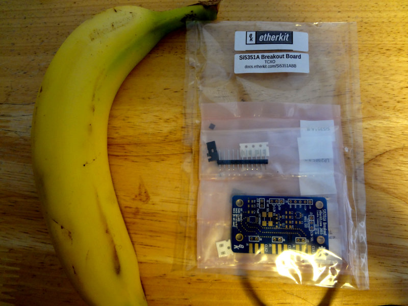
Spent some time at the workbench putting together the Etherkit Si5351 board that arrived the other day.

Etherkit Si5351 breakout board

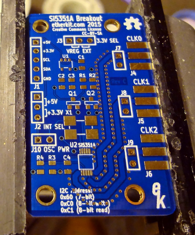
Although it’s pretty much all surface mount, everything is on one side of the board, and the part count is relatively low so assembly is pretty easy. The fine pitch of the Si5351 chip makes soldering it more challenging, but generous use of solder flux helped the solder flow where it was supposed to go.

Si5351 IC soldered on

After the Si5351 came the TCXO crystal. The large pads make this part relatively easy to solder.

TCXO crystal
TCXO crystal

The transistors and 3.3V voltage regulator were the next components to get soldered on. These were pretty easy to do. As with the Si5351, a good amount of solder flux helps with the voltage regulator.

Transistors and voltage regulators

The remaining passive components (4 capacitors and 4 resistors) finish up the surface mount components. These are pretty easy to solder on. Tack down one side with a bit of solder, then solder the other side.

Caps and resistors
Caps and resistors

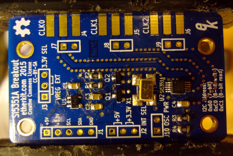
With all the surface mount components on the board, that leaves just the header pins and the edge mount SMA connectors. Easy peasy.

Header pins and SMA connectors

And with that, the Etherkit Si5351 breakout board is finished! Next step is to connect it up to one of my *duinos and see if it works.

I have two more boards to assemble, and some of the things I learned assembling this one should make the other two a little smoother.

Si5351 breakout boards arrived!

The Etherkit Si5351 breakout boards finally arrived!

Etherkit Si5351 breakout boards
Etherkit Si5351 breakout boards (Banana for scale)

It took the Pony ExpressUSPS 13 days to deliver the package from Oregon to South Carolina. According to USPS tracking, it took 7 days for the package to surface in Ft. Worth TX. Then it disappeared for another 5 days before resurfacing in Columbia SC and then being delivered to the house the next day. Using Google Maps to get a rough idea of the distance, the package traveled about 3100 miles in 13 days, or about 10 miles/hour.

I’m looking forward to assembling the boards. Jason did a really good job with the boards. I think the most challenging part will be soldering on the Si5351 chip itself. It’s a pretty tiny piece.

Si5351 breakout board (banana for scale)

I don’t have any plans for the breakout boards yet, but there are the usual suspects: SWR meter/antenna analyzer, signal generator, and maybe eventually a radio.

Etherkit SI5351 breakout board

Pictures of the assembly coming up.

Coils

Time to see if I can build myself a crystal radio set. Or two. Or three.

I decided rather than demonstrate building a radio at the Charleston Library’s DIYFest, it would be easier to bring in some examples of some simple crystal radios that could be built using stuff easily obtained around the house. Found three nice cylindrical objects and started winding magnet wire.

The inductance of an air wound coil, according to Section 2.12.1 of the 2014 ARRL Handbook, is approximately

L (μH) = d2n2/(18d + 40l)

where d is the coil diameter in inches, l is the coil length in inches and n is the number of turns. Converting it to use more sensible metric units, it becomes

L (μH) = d2n2/(45.72d + 101.6l)

where d and l are in centimeters.

The first coil is 182 turns around a toilet paper tube. d = 4.5 cm, l = 6.7 cm, n = 182, and L = 757 μH.

First coil - 182 turns, d=4.5cm l=6.7cm
First coil – 182 turns, d=4.5cm l=6.7cm

Coil #2 is 110 turns around the cardboard core of a packing tape roll. d = 8 cm, l = 4 cm, n = 110, and L = 1003 μH.

Coil #2 - 110 turns, d=8cm, l=4cm
Coil #2 – 110 turns, d=8cm, l=4cm

Coil #3 is 118 turns around an empty plastic pill bottle. d = 4.8 cm, l = 4.1 cm, n = 118, and L = 504 μH.

Coil #3, 118 turns, d=4.8cm, l=4.1cm

This is the basic schematic I’m planning on using.

radio schematic
radio schematic

I want the radios to be able to tune in the AM broadcast band (540-1710 kHz) so the capacitance I’ll need for coils #1 and #2 is around 10 pF and around 17 pF for coil #3.

Since I have three coils, I think I’ll make one with a variable inductor, one with a variable capacitor, and one with a variable inductor and capacitor.

I don’t have any high impedance earpieces (I’ve seen some builds say you can use a telephone handset though), so I might add an amplifier or impedance matching transformer and see if I can get regular headphones to work.

Si5351 breakout board

Jason/NT7S launched the crowdfunding campaign for his version of an Si5351 breakout board last night, and already this morning it’s at over 150%. The stretch goal at $1 500 involves spending some more time on the software library to make the board easier to use.

It’s a neat little oscillator chip that seems to provide a lot of capabilities for not a lot of money. He’s been documenting his investigations on the chip at his blog for the past year now, including building a couple of receivers and transceivers around the Si5351.

The Si5351A is quite a capable IC at a very modest price. It is a PLL clock generator with three independent outputs which can each generate a separate signal from 8 kHz to 160 MHz. A 25 or 27 MHz reference oscillator is used for the two internal PLLs (the Etherkit breakout board uses a 25 MHz reference oscillator), which allows the user to choose the amount of frequency stability and accuracy required.

Go check out the Si5351 breakout board campaign on Indiegogo, and pick one up if it’s something you’ll find useful in an upcoming project.

Ugly construction attempt

My first attempt at building a circuit using the ugly construction technique. It’s supposed to be a simple oscillator circuit using a J310 transistor.

One of the advantages of ugly construction is that if you’re working from a schematic or circuit drawing, building is pretty easy. I found that soldering components to the copper clad required a bit of patience, because it’s essentially a very large heat sink. Put the soldering iron on the copper clad, add solder until you get a good sized pool, leave the soldering iron in place and place the component.

For this particular circuit, Vcc is applied to the big resistor with the free lead and output is off the capacitor with the free lead. I soldered on a piece of wire to make the ground connection easier. Haven’t applied power to test it out yet. Will see if it works later on.