Connecting the microphone

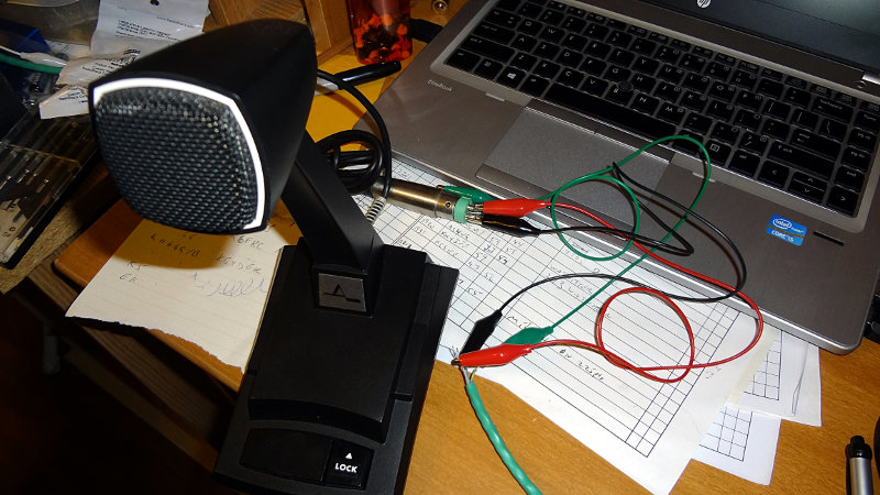
It took a little bit of work and puzzling out wires, but I managed to get the microphone (temporarily) wired up to the radio. In the process, I learned a few things.

  • If you look up the pin numbering for the RJ45 connector (apparently the corrent term is 8P8C), most diagrams have pin 1 on the left side and pin 8 on the right side.
  • Kenwood numbers the modular connector used for the microphone on the TS-480SAT with pin 1 on the right side and pin 8 on the left side.
  • The white and green wires in the Astatic 877L are connected to the PTT switch, but not to anything else. Posts on internet forums say that with Astatic microphones, the white wire is usually the MIC AUDIO line. In the case of this microphone, that’s not true. The only wires that count are the red, black and ground/shield wires.
  • Ignore the Internet and stick to the microphone wiring label.

I had a short piece of CAT6 ethernet cable on hand, so I cut that in two pieces, stripped the ends and used some jumper wires to connect the microphone to the appropriate wires on the ethernet cable.

Temporary microphone wiring
Microphone wireCAT 6 wireFunctionPin (Kenwood)Pin (RJ45)
ShieldGreen/white stripeGND36
BlackBlue/white stripeMIC GND54
RedWhite/blue stripePTT45
RedWhite/green stripeMIC63

Wired up like this, the microphone seems to work. With TX monitoring on the radio turned on, I can hear myself pretty nicely through the speaker. The meters on the radio move when I talk. I wasn’t able to make any contacts on the radio to get any kind of signal report though.

With only three connections to make, it should be pretty simple to replace the existing microphone cord with my length of CAT6 cable. The only thing I don’t like about this wiring scheme is that it puts mic audio on the radio’s PTT line. Although the radio didn’t seem to protest during my testing, I’m not sure that’s a good thing.

I think I’ll test out this alternative wiring as well

Microphone wireCAT6 wireFunctionPin (Kenwood)Pin (RJ45)
Shield/Green (F)Green/white stripeGND36
White (E)White/blue stripePTT45
Black (A)Blue/white stripeMIC GND54
Red (C)White/green stripeMIC63

This will separate the mic audio and the PTT lines which, from the radio’s perspective, seems to make more sense.

I wonder if I’ve got a rocker switch in the junk box that I could connect the UP/DOWN lines to. I think there’s enough room in the mic base where I could make an opening and add it in.

Another Heathkit IG-102 mod

Spent another evening poking around inside the Heathkit IG-102 signal generator, this time with schematic in hand and probing around with my DMM to check voltages in various places. I wanted to make sure everything was working ok, and it seems to be. The voltages I was getting were all pretty close (within 10%) of what was printed on the schematic.

I also replaced the original 60s or 70s era power cord with a polarized power cord (harvested from I don’t remember what now). It was a simple replacement and probably not critical but I figured having a new(-ish) cord might make it a little more electrically safe. The hard part was unsoldering the old cord and getting the plastic strain relief thing out of the chassis.

I was able to set my HT to a few frequencies in the 10-30 MHz range and heard tones when I adjusted the signal generator to those frequencies. That seems like a good sign it’s working.

Poking around inside the Astron RS-35A

Spent some time poking around inside my Astron PS with a schematic in hand. It was interesting having another look inside and examining things a little closer.

With the schematic, I was able to identify a few components that I didn’t immediately recognize. At the AC input side, I found a varistor, VR1, (150L10) in between the fuse and the switch, rather than between the switch and the transformer as shown on the schematic. None of the schematics I see show it like that so it makes me wonder if the PS has had some “work” done to it.

Astron RS-35A power input

Here’s the wiring on the AC input side

Astron RS-35A power input

The schematic shows a 64 mF 25V electrolytic capactor (C5) filtering the output of the transformer, but in my unit that was accomplished with two large 32 mF capacitors in parallel. Probably easier that way. A 64 mF capacitor would be pretty big.

Power filtering caps

Output from the transformer goes into the control board which handles regulating the output of the power supply.

Power regulation board

The 2N3771 pass transistors are easily seen on the back of the power supply where the heatsink takes up pretty much the whole rear panel. On the inside 0.05 Ω 5W power resistors hang off them.

2N3771 pass transistors

The high current output of the transformer goes into a couple of 1N1184A power diodes that appear to be set up to do simple half wave rectification. Schematics in later models show a pair of bridge rectifiers doing full wave rectification on the transformer output. The newer models probably produce a lot less ripple in the output waveform than mine does. My power supply has the 1N1184A diodes (CR101 and CR102) bolted to the chassis. The thick yellow wires feed the diodes and the thinner orange wires go to the control board. The green wire is a center tap off the transformer and goes to the negative terminal of one of the 32mF capacitors.

1N1184A power diodes

Also bolted to the chassis is a TIP29A transistor (Q2) using the chassis as a heat sink. Later models have this on the control board with a small heat sink.

Another diode looking thing is bolted to the chassis, which according to the schematic is a S0535H diode (SCR1). I can’t confirm this using the text stamped on it though.

S0535H SCR diode
S0535H SCR diode

This leads to the output of the power supply, which has a 2200 μF capacitor (C101) across the output terminals. Where the schematic shows just a single 10 nF capacitor also across the output terminals, mine has what appears to be two 47 nF capacitors (some older schematics show them as 10 nF caps) each connecting one terminal of the 2200 μF capacitor to ground, along with a 3000 Ω resistor from the negative terminal to ground. This is something that I saw on earlier schematics, but not on later ones. Apparently they’re for filtering out sags or spikes if the load on the output changes.

Astron RS-35A power output

Astron PS mods

I’ve been pondering some modifications to make to my Astron power supply. The first mod I considered was replacing the nut/bolt terminals with Anderson power pole connectors, but it looks like that will require replacing some wiring and what appears to be additional filtering components which I think I’d rather not do in case I mess things up. Plus I’d also have to square out the round holes for the power pole terminals. I think I’ll just make up some pigtails with power pole connectors instead.

Found a fair bit of info and interesting looking mods to Astron power supplies at the Repeater Builder site that I might try. The in-rush current reducer mod looks simple enough and while mine has never tripped the breaker when I flip the power switch, it seems like a good idea to have in place.

I think it would also be neat to have a volt and current meter on the PS to monitor the output. There’s plenty of room on the front panel of the PS for meters, but my metal working tools and skills are limited and I’m not sure I’d be able to do a proper job yet. I think the easiest way for me to add the meters is make a separate enclosure or panel for them that will sit on top of the PS. That should be easy enough to do.

One interesting thing that I noted while browsing the Astron part of the Repeater Builder site is that all of the schematics for the RS-35M/RS-35A they have show only one large 2.2 mF filtering capacitor while there are two in my PS. Don’t know if that’s an addition to newer models, or if it was someone else’s mod.

After taking another look at the first pictures I took, it looks like there may already be a thermistor (the red thing that I think looks like a thermistor anyway) added in the circuit.

Think I’ll open it up again and have a closer look at what’s inside.

Coils!

In addition to the air variable capacitors, three of the parts bins contained a bunch of pre-wound antenna coils, including these that looked unused. One of them even had an instruction sheet.

Calrad CLS Loopstick.

Calrad CLS loopstick

They consist of two coils, one wound on top of the other and what seems to be a ferrite rod inside that can be tuned by turning the screwdriver or even a knob at the other end.

Calrad CLS loopstick

One was also in a box, a Miller A-5495-A with two separate coils and a capacitor. Looks like it has a tuning range of 540 – 1700 Hz, which is the AM broadcast band.

Miller A-5495-A coil

This one was tunable as well by turning the screw at the end.

Miller A-5495-A coil

Now, if I can find some Ge diodes, I wonder if I could use these in a crystal radio