A QRP dummy load

Every ham needs a dummy load, right? I’ve been wanting to build a small little dummy load for QRP for a while so it became one of my day-off projects today. The dummy load kit from Hendricks QRP Kits served as my model for this build.

I emptied my inventory of 1kΩ 1/2W resistors and scrounged up 5 more 1kΩ 1/4W resistors out of the bag of goodies from Jason/NT7S (saved me a trip to Radio Shack). A total of 20 resistors went into the dummy load: 15 1/2W and 5 1/4W for a total theoretical power dissipation of 8.25W.

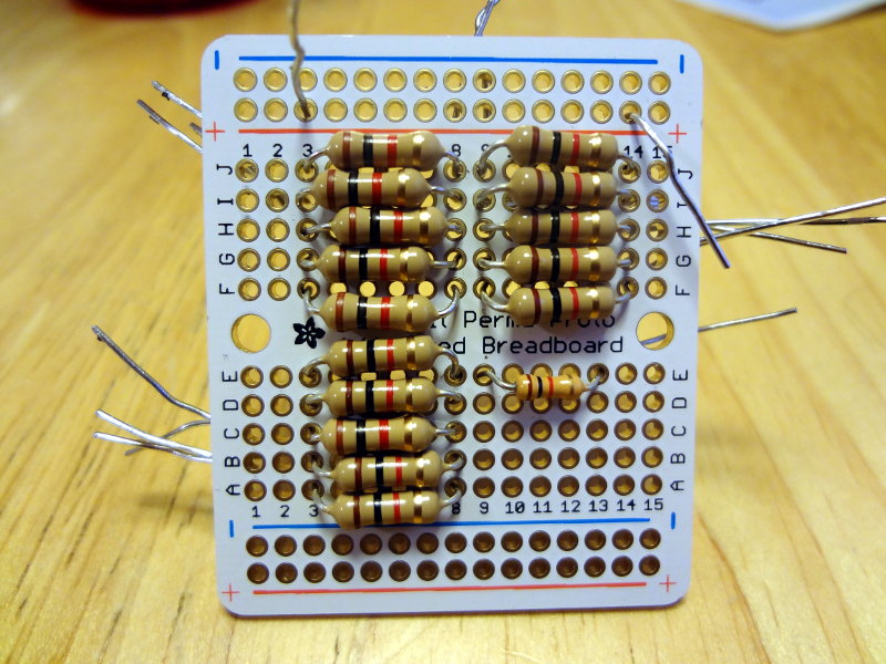
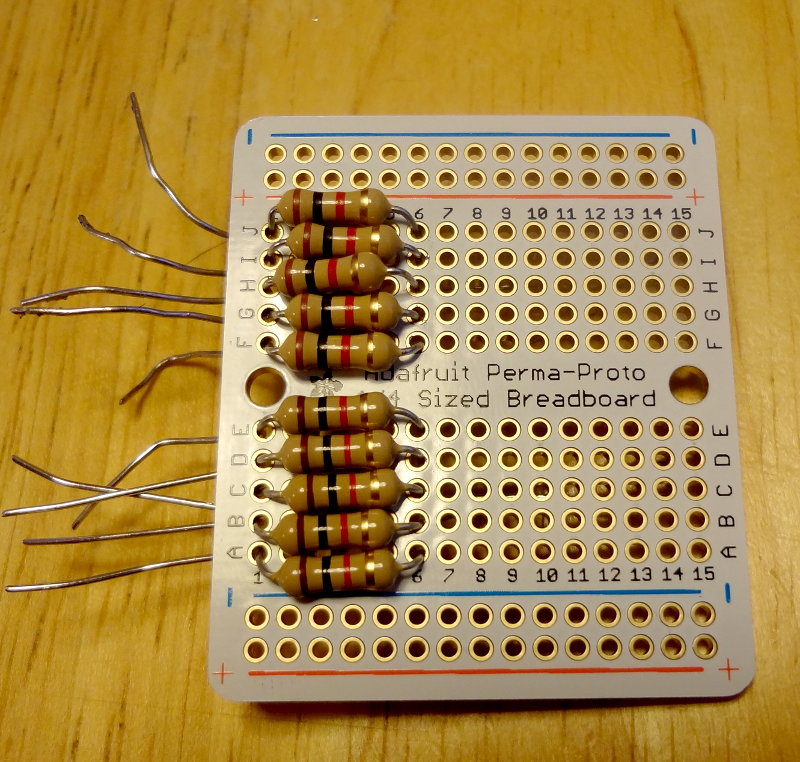
The platform for my dummy load is an Adafruit quarter size Perma-Proto board which I’ve really enjoyed working with. Here it is with half of the resistors placed on the board, but not soldered in yet.

Dummy load half complete

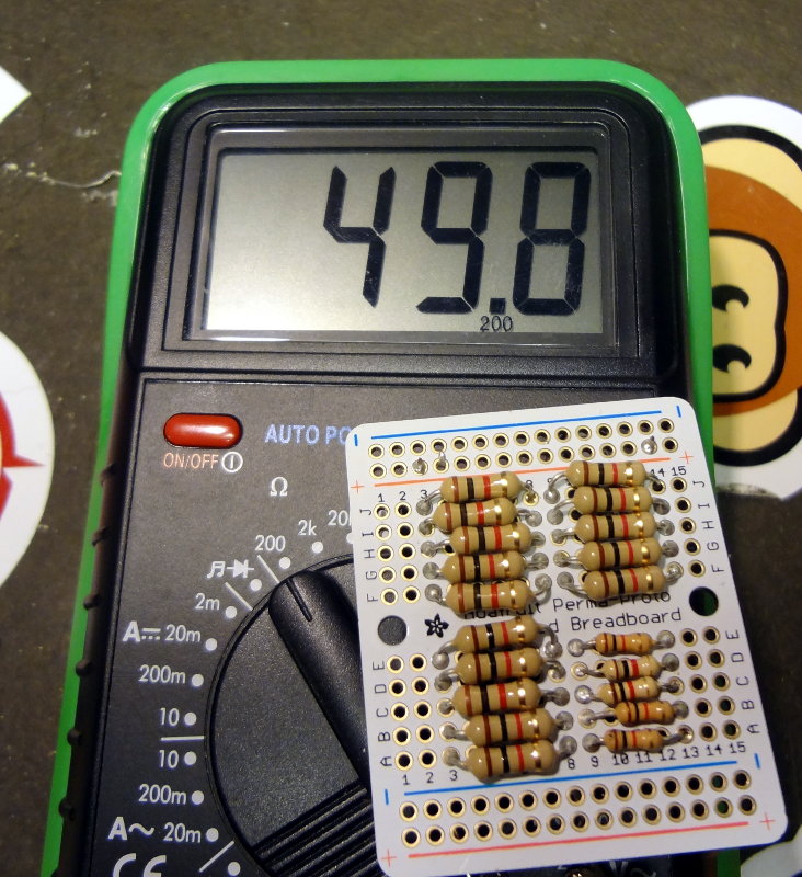
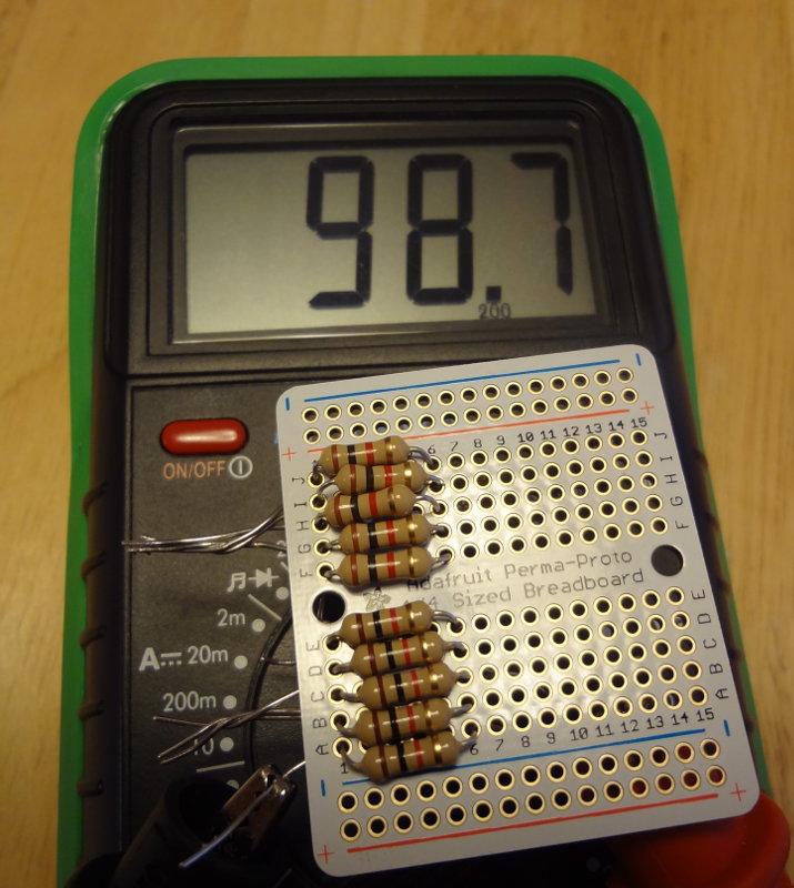
Just under 100Ω with half the resistors in, so my layout is working.

Almost 100 ohms!
Almost 100 ohms!

It was a bit of a squeeze to get those 1/2W resistors in, but it worked. The 1/4W resistors fit easier into each row.

Tight fit
Tight fit

With everything soldered into place, I measure just under 50Ω. Pretty good.

Pretty close to 50 ohms

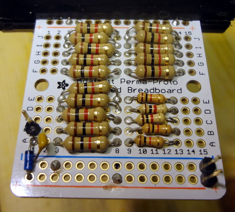
The Hendricks dummy load also lets you use measure power output using a volt meter so I added that part in as well. A 1N5711 diode (again from the bag of goodies from Jason), a 10 nF cap and some header pins finishes the dummy load.

Completed dummy load

The two pins at the lower right of the board are for the connection to the radio, and the single pin on the left side is the voltage/power measurement point. All that remains now is to find an enclosure to put it in and add a convenient way to connect to the radio and access the measuring points.
Fluke 75 DMM repair

I think my skills at the workbench have progressed to the point where I’m feeling pretty good about being able to make minor repairs to some of my electronic gadgets.

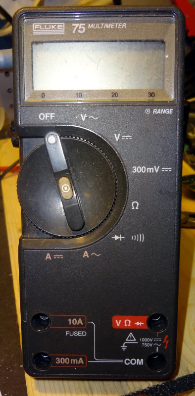
I’ve had this Fluke 75 autoranging DMM sitting in a toolbox for a bunch of years because it never worked properly. Brought it out to the workbench the morning and cracked it open to find the 9V battery inside had leaked, and the battery posts had corroded.

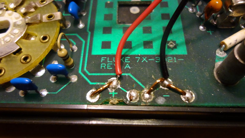
Should be a pretty easy fix. I’ve got some 9V battery connectors with leads in the parts bin. Heated up the soldering iron and removed the old posts, then soldered in the leads for the 9V connector. The original battery posts had three connections, so I used some hookup wire to jumper the other two connections to where the connector leads were going to go.

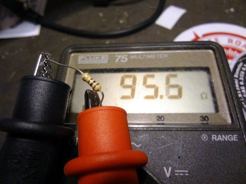
Closed everything back up and fired up the meter. Yay, back in business!

CRX1 container

I thought the CRX1 fit pretty  nicely in that parts bin, so I decided to make it into a container (can’t really call it an enclosure) for the board. It’s not an elegant enclosure like the kind Dave/AA7EE makes, but it works out pretty well, and shows off the board nicely. Maybe when I get some enclosure making skill levels, I’ll make a new one.

CRX1 container
CRX1 container

I was originally going to get some standoffs to secure the board to the bin, but then I thought it might be nice for there to be a bit of weight so that it would sit a little more securely. I cut a piece of 1×3″ board to fit and screwed it to the bin, then screwed the CRX1 to the board.

CRX1 side
CRX1 side
CRX1 side
CRX1 side

Now I need to find some rubber feet for the bottom of the bin and some knobs for the gain and tuning pots.

Sound card interface troubleshooting

A little more troubleshooting on the sound card interface moved the problem from the radio settings (which I think I have set properly…blog post about my radio settings to follow) to the interface board.

If I use fldigi to transmit, nothing happens on the radio. PTT was being triggered, but I think that was flrig triggering the PTT over the serial port, and the radio would have been listening on the mic jack instead of the data port.

If I ground the collector lead of the transistor on the board to trigger PTT on the data port and then tell fldigi to transmit, then I hear transmitted sounds on the radio and there’s activity on the signal meter.

For some reason, the audio signal going out into the PTT part of the circuit isn’t enough to make the transistor switch and ground the collector pin.

I’ll have to go through that part of the circuit to make sure i have all the components right and wired up properly. Worst case scenario I’ll just wire in a button switch to manually ground the collector pin for manual PTT.

Workbench acquisitions

Purchased a few more supplies for the workbench that arrived in the mail today.

Workbench acquisitions

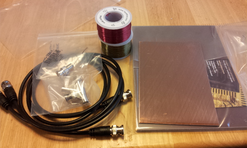
A couple of coax jumper cables and BNC adapters for connecting things to the oscilloscope, 2 1000′ spools of heat strippable magnet wire and 10 pieces of single sided copper clad PCB.

Looking forward to my first builds on the copper clad.