Power supply: Out to the control board

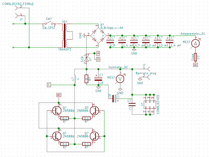
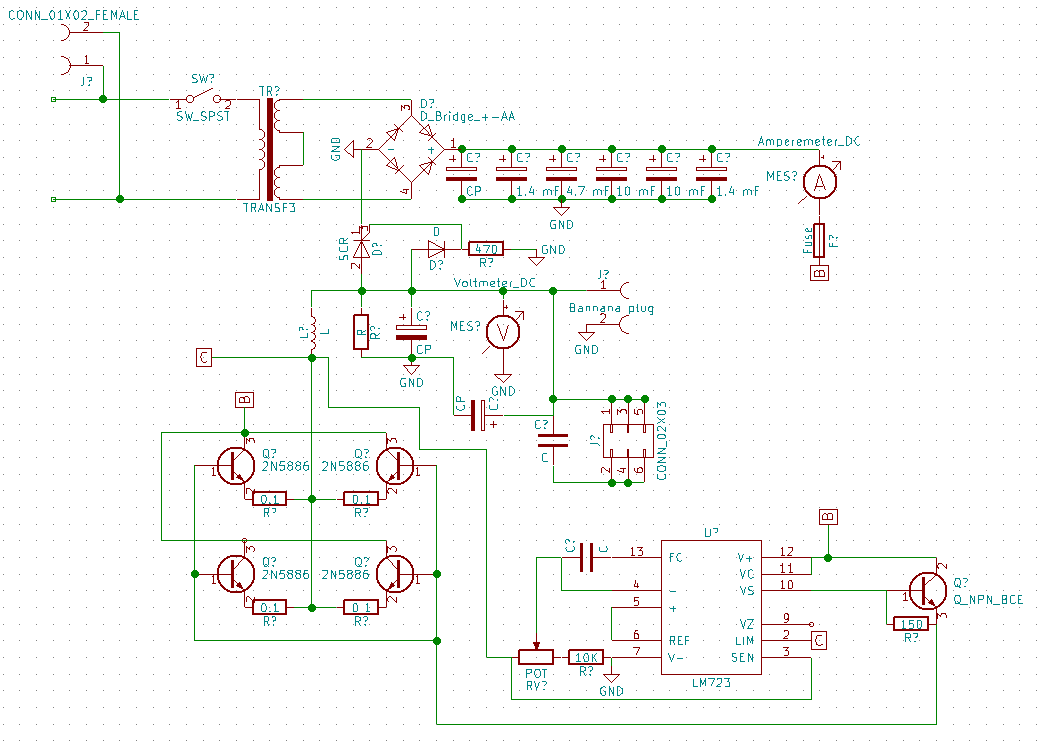
I’ve finished tracing the power supply schematic out to the control board. I’ll go through it once or twice more to make sure I’ve got everything right, but I think I’ve got a fairly complete schematic of the power supply now.

Here’s the schematic so far.

Power supply schematic

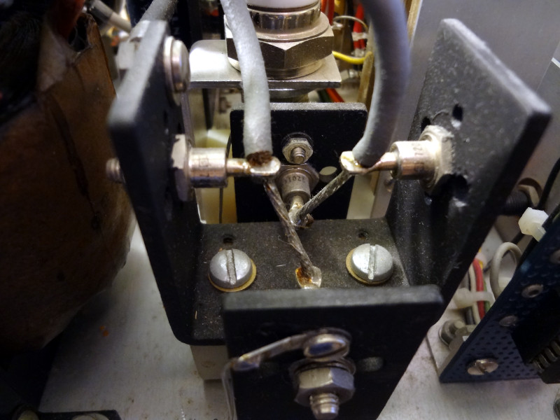
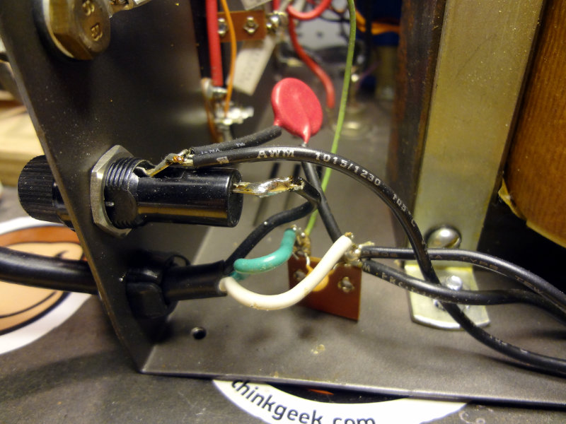
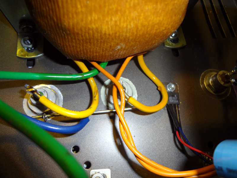
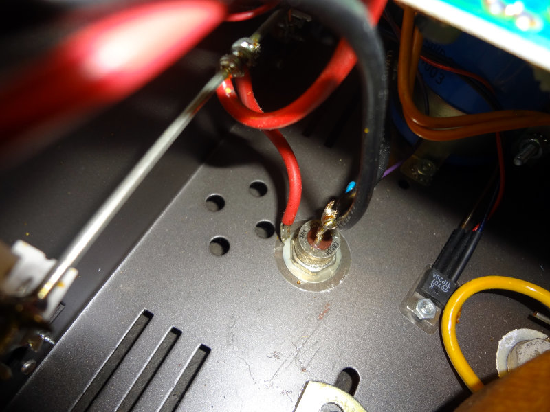
I did run into an anonymous transistor type part with a red case that I wasn’t able to identify. Whatever markings were on it have been rubbed off, so there’s no way to really identify it anymore.

Mystery transistor
Mystery transistor

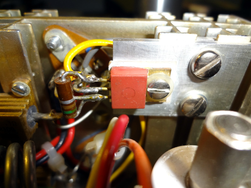
The base of the transistor (I’m assuming it’s the base anyway) is connected to pin 10 of the 723 voltage regulator while the emitter is connected to the bases of the power transistors. The collector goes to pin 12 of the 723 and the collectors of the power transistors. Checking with schematics for my Astron RS-35, there’s a TIP29 transistor in roughly the same spot, so I’m reasonably confident this mystery part is an NPN transistor of some kind.

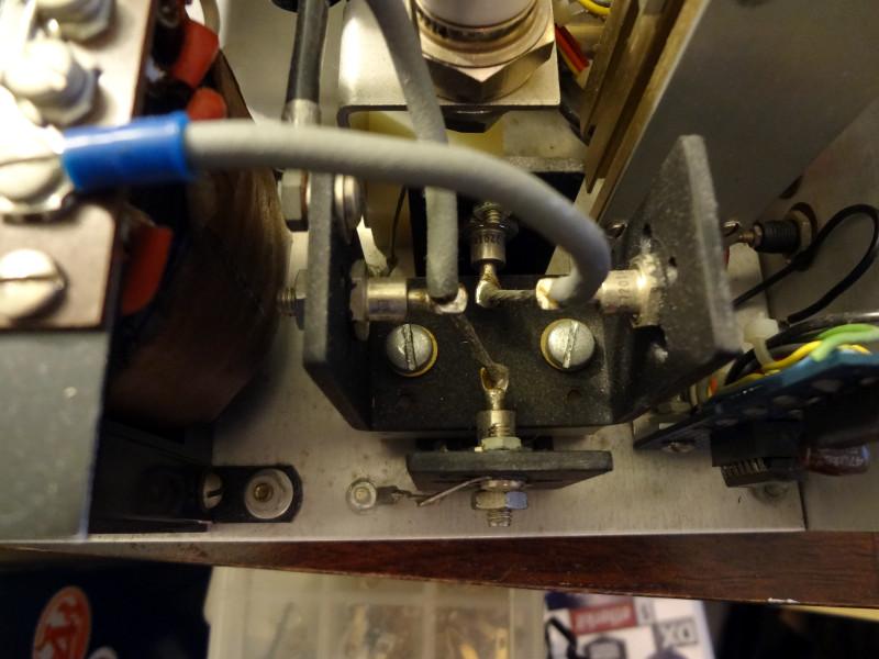
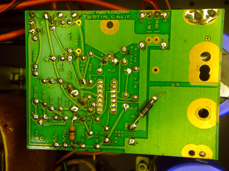
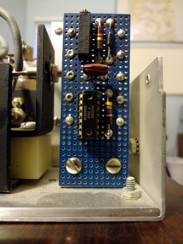
Tracing out the control board was a bit tricky, but I think I managed to get it right (I think I’m missing the diode on the schematic though). I’ll need to recheck where the wires coming off the control board go in the rest of the power supply.

Power supply control board

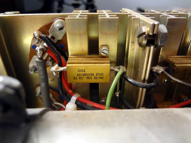
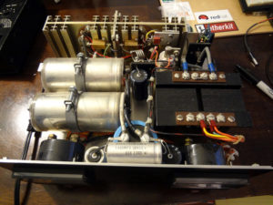
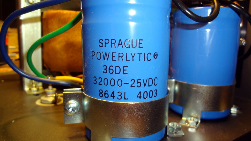
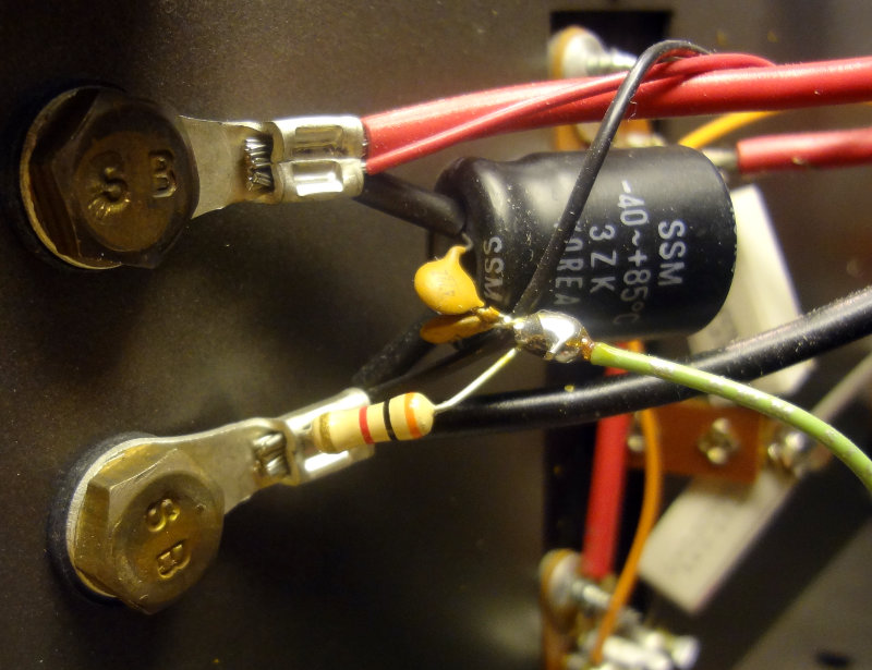
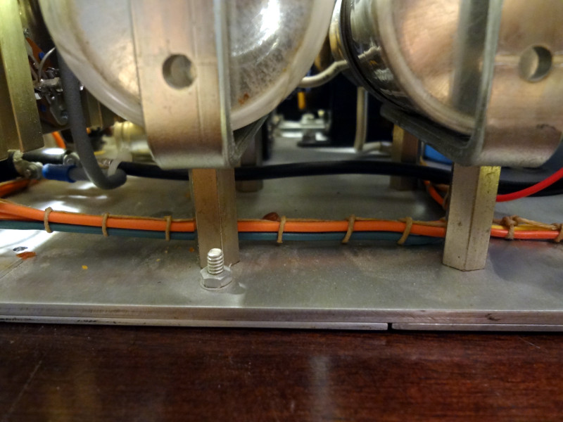
Quite impressed with the way this power supply was put together. Everything is soldered or screwed together nice and cleanly, and the wires are nicely dressed and bundled together with zip ties and string.

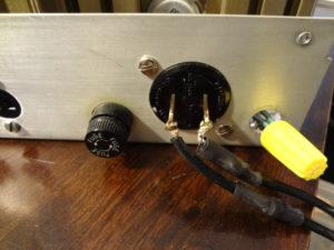
Except for the blown fuse, I don’t see anything obviously wrong with the power supply. I think I will look into replacing that AC input plug though before I try applying power to this thing.

Power supply: Power transistors

I’ve traced the power supply schematic past the SCR and out to the power transistors that are attached to the big heat sink. This part of the schematic might be a little questionable because a lot of the wires are covered up or obscured by other components and a little harder to follow.

The schematic so far:

Power supply schematic

I’m up to the control board now. It’s small, but has a lot of wires coming in and out of it. Fortuantely it’s all point to point wiring on perfboard, so I don’t have to follow any PCB traces.

Power supply project: Input and filtering

Tracing out a schematic for this power supply has been pretty fun so far. It’s also been a good excuse to learn how to use KiCad.

So far I’ve made it past the rectifier and filtering capacitors up to the power transistors. I’m pretty impressed with the way the innards of this thing are put together. The bridge rectifier part took me a bit to figure out until I realized there were two different stud mount diodes in it.

Rectifier diodes
Rectifier diodes
Rectifier diodes
Rectifier diodes

I’ve come across a couple types of components that took me some searching to figure out what they were (still not quite sure what one of them is). This one in particular is one I haven’t been able to identify.

Mystery component. Diode? Transistor?

It’s connected to one of the outputs of the bridge rectifier and the control board at the top. At the bottom it’s connected to an air core inductor and parts that lead to the 2N5886 power transistors. A Google search of the numbers printed on it take me to a single page at a store that has it listed as a rectifier diode.

This is the schematic I’ve cobbled together so far. Things start to get a bit confusing after the rectifier, but I think it’s reasonably accurate.

Power supply schematic

I wasn’t able to find symbols for everything in the KiCad library, particularly for the connectors, so I just used something that looked reasonable.

This has been a fun exercise so far. The power transistor section will probably take me a while to figure out.

Power supply project

The dead power supply I picked up at the TARC swap meet last year has been sitting in a couple of closets for the past year, and now I’m finally getting around to poking around inside.

Power supply front panel

The innards of the power supply look pretty good. Everything looks pretty clean, no scorch marks, and hardly any dust.

Power supply innards

Looking at the back panel doesn’t inspire much confidence though. Looks like at some point someone soldered a regular power cable to the original (I think) AC input and covered it with heat shrink. I might have to do something about that when I start working on the power supply.

Back panel AC in
Back panel AC in

So far everything looks in pretty good shape. Not sure what the problem with it is (aside from a blown fuse), but before I dive in and start mucking around, I’m going to see if I can reverse engineer a schematic for the power supply. There aren’t any labels on the power supply so I can’t look anything up. Should be a fun exercise.

Poking around inside the Astron RS-35A

Spent some time poking around inside my Astron PS with a schematic in hand. It was interesting having another look inside and examining things a little closer.

With the schematic, I was able to identify a few components that I didn’t immediately recognize. At the AC input side, I found a varistor, VR1, (150L10) in between the fuse and the switch, rather than between the switch and the transformer as shown on the schematic. None of the schematics I see show it like that so it makes me wonder if the PS has had some “work” done to it.

Astron RS-35A power input

Here’s the wiring on the AC input side

Astron RS-35A power input

The schematic shows a 64 mF 25V electrolytic capactor (C5) filtering the output of the transformer, but in my unit that was accomplished with two large 32 mF capacitors in parallel. Probably easier that way. A 64 mF capacitor would be pretty big.

Power filtering caps

Output from the transformer goes into the control board which handles regulating the output of the power supply.

Power regulation board

The 2N3771 pass transistors are easily seen on the back of the power supply where the heatsink takes up pretty much the whole rear panel. On the inside 0.05 Ω 5W power resistors hang off them.

2N3771 pass transistors

The high current output of the transformer goes into a couple of 1N1184A power diodes that appear to be set up to do simple half wave rectification. Schematics in later models show a pair of bridge rectifiers doing full wave rectification on the transformer output. The newer models probably produce a lot less ripple in the output waveform than mine does. My power supply has the 1N1184A diodes (CR101 and CR102) bolted to the chassis. The thick yellow wires feed the diodes and the thinner orange wires go to the control board. The green wire is a center tap off the transformer and goes to the negative terminal of one of the 32mF capacitors.

1N1184A power diodes

Also bolted to the chassis is a TIP29A transistor (Q2) using the chassis as a heat sink. Later models have this on the control board with a small heat sink.

Another diode looking thing is bolted to the chassis, which according to the schematic is a S0535H diode (SCR1). I can’t confirm this using the text stamped on it though.

S0535H SCR diode
S0535H SCR diode

This leads to the output of the power supply, which has a 2200 μF capacitor (C101) across the output terminals. Where the schematic shows just a single 10 nF capacitor also across the output terminals, mine has what appears to be two 47 nF capacitors (some older schematics show them as 10 nF caps) each connecting one terminal of the 2200 μF capacitor to ground, along with a 3000 Ω resistor from the negative terminal to ground. This is something that I saw on earlier schematics, but not on later ones. Apparently they’re for filtering out sags or spikes if the load on the output changes.

Astron RS-35A power output