Etherkit EtherKeyer Mini printed circuit boardKM4CFT 3D printed CW paddlesKM4CFT 3D printed CW paddles
I’ll need to see if I’ve got a spare TRS cord lying around to use with the paddle.
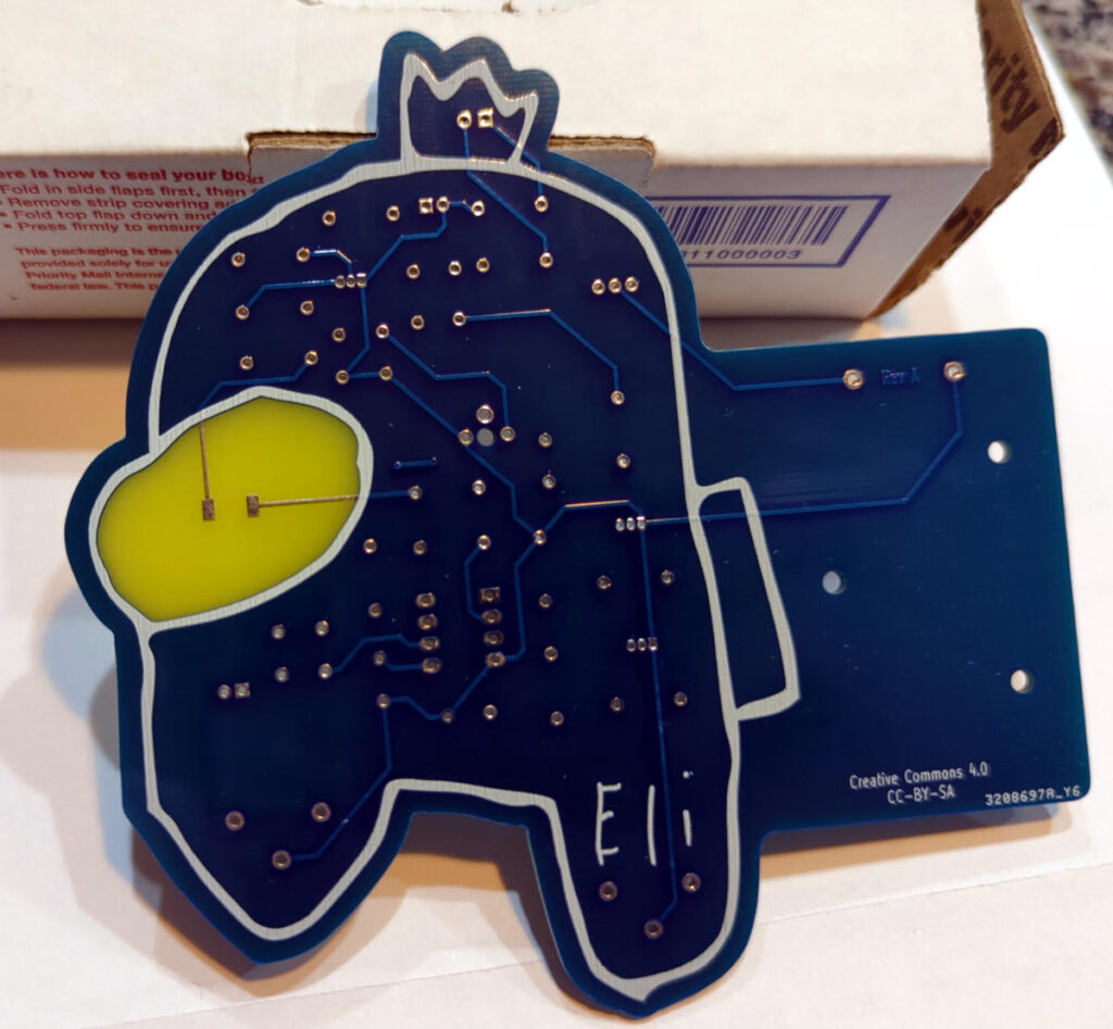
The other board he sent along was a code practice oscillator board (the Etherkit CPO Among Us edition).
Printed circuit board in the shape of a character from the video game Among UsPrinted circuit board in the shape of a character from the video game Among Us
These should make for a fun weekend project.
Jason’s got some fun looking things in the works these days. Go see what he’s been up to on his Applied Etherics Substack.
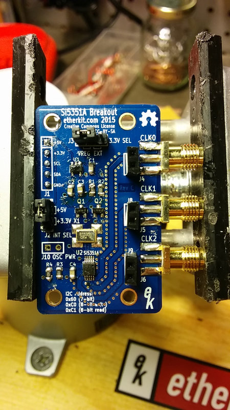
Unlike the previous boards I bought (from the crowdfunding campaign), the latest versions now come fully assembled except for the header pins. If the thought of soldering tiny surface mount devices was keeping you from trying the breakout board, worry no more.
The 10 mW WSPR beacon app note looks pretty interesting, and I think it would be fun to try to get one set up once we’re in the new house. I’d love to see how far it could be heard.
We’ll hopefully be in the new house in a few more weeks. I’m looking forward to getting the shack and workshop set up again so I can get to playing.
The Si5351 breakout boards all work, at least according to the frequency counter, so I thought I’d put the oscilloscope on one to see what was coming out. I just connected the output of the Si5351 board straight to the oscilloscope using an SMA/BNC pigtail. I’m sure it’s a totally incorrect way of doing it, but all I wanted to see was if I got a waveform and if it changed when I changed the Si5351 frequency.
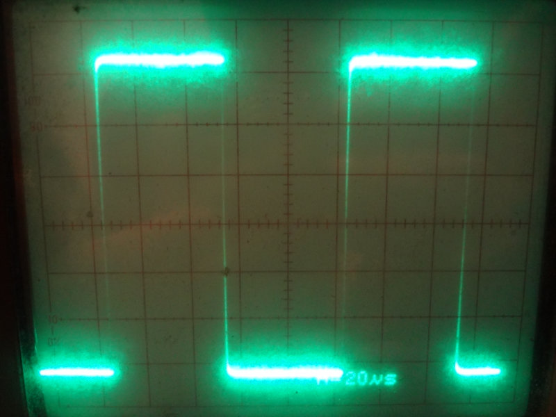
I’ve been told that the Si5351 output is a square wave, and at kHz frequencies, that’s what I get. This is the 10 kHz waveform. Nice looking square waves.
Etherkit Si5351 10 kHz waveform on the oscilloscope
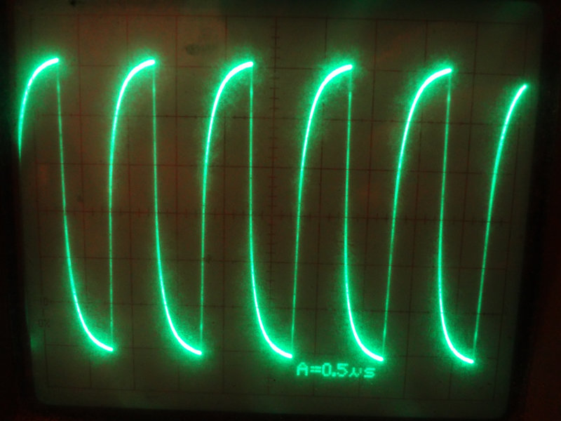
Going up a few orders of magnitude to 1MHz, the shape of the waveform loses its squareness, most likely due to the way I’ve connected things (impedance mismatch, improper loading and all that). But, as the time base shows, it’s a much higher frequency signal.
1MHz wave form
At 10 MHz, there’s even more distortion of the waveform, but definitely higher frequency.
10MHz waveform
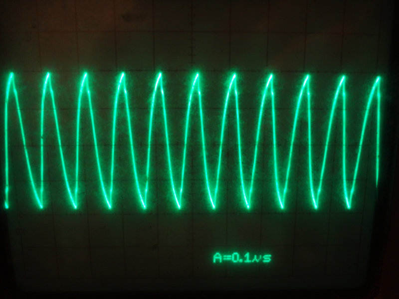
Up at 20MHz, things are looking pretty triangular.
20MHz wave form
So, TIL:
My Si5351 board really works! Yay!
You can’t just connect things willy-nilly to an oscilloscope and expect good results. (I already knew this, just wasn’t important for this purpose.)
There are still some things I need to learn about using this particular oscilloscope.
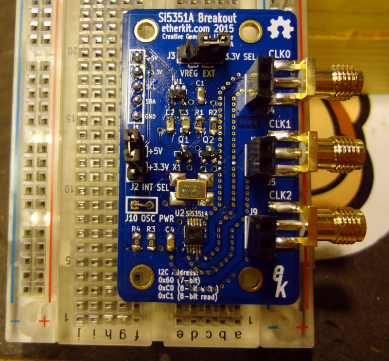
Finished assembling a non-TCXO version of the EtherkitSi5351 breakout board today. With three boards worth of experience behind my back now, this one went pretty smoothly. Set this one up to use in a breadboard like board #3.
Etherkit Si5351 board non-TCXO version
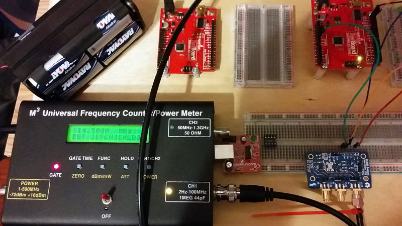
Then it was off to test them out. I used Jason’s Si5351 Arduino library (as of this writing, the ‘jason’ branch is the most current one) and one of the example sketches with one of my *duino boards, connected the M3 frequency counter and wired everything up.
Much to my surprise, the first board (with the TCXO) worked, and the frequency was pretty much bang on, at least to the resolution the M3 meter is capable of.
Testing the Etherkit Si5351 board
The non-TCXO board I assembled today was off by a bit (~900 Hz), but Jason says that’s normal for the regular oscillator.
The other two TCXO boards worked as well and were right on frequency.
Testing the Etherkit Si5351 boards
Now I need to work on more precise frequency measurements so I can work out the calibration offset for each of the boards.
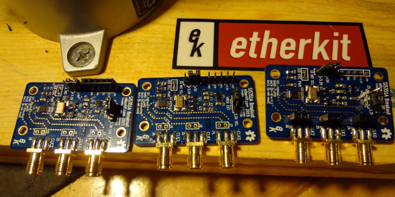
Finished assembling the last of the EtherkitSi5351A breakout boards I received from Jason‘s Indiegogo campaign. Since I had three of them to play with, I decided to do a few different configurations.
Etherkit Si5351 breakout boards 3 ways
Board #1 is a pretty conventional setup with the header pins pointing up. Lays flat on a surface and could be mounted inside an enclosure if needed.
Etherkit Si5351 board with conventional pin layout
Board #2 I used female header pins to make interfacing with my *duino boards easier, since almost all the jumper wires I have are male/male.
Etherkit Si5351 board using female connector pins
Board #3 I set up to make it easy to use with breadboards. The header pins are pointed “down” so that I can stick the breakout board into a regular breadboard. I also added female headers to the output in addition to the SMA connectors.
Etherkit Si5351 board with pins down for breadboard use
I still need to test the boards out to make sure they actually work. I think if I’m going to have any problems with the boards, it will probably be with the soldering of the Si5351A chip.