CC1 face plates

Update: After a couple of iterations with paper, some of the measurements were adjusted and the drawing updated. I’m pretty sure the measurements are accurate and will serve to help other CC1 builders create a drilling template for their build. As always, keep in mind the “measure twice, cut once” principle. YMMV. Links to my templates are at the end of the post. Feel free to use them as a starting point for your CC1 build.


In preparation for drilling out the holes in the face plates for the CC1 enclosure, I used my digital calipers to measure the distances to the center of each of the connectors that would need a hole.

First I started measuring while holding it in my hand, but I realized there’s a little bit of play when the board is in the enclosure and measurements would change depending on how I was holding it.

I decided to place CC1 and enclosure on the table and starting with the left-most connector (A), measure it’s position relative to the left and bottom edges of the enclosure. For the remaining connections, I just measured the offset from the first one since their positions are fixed. Seemed like the most accurate way of doing things.

In Dia, I made this drawing up

CC1 face plate template

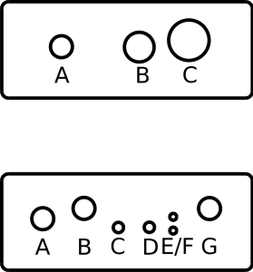
The face plates are 74mm x 29mm. The top one is the back plate with the largest hole corresponding to the BNC jack. The bottom one is for the front plate. The Dia version should be to scale, but when I printed it, it was just a tiny bit short along the x-axis. Apparently printer scaling and computer scaling is a tiny bit different. It should still be pretty close to use as a template though. Will try cutting it the paper version to see how well it fits before I start drilling.

These are the measurements I came up with

Front plate.

Measurement for A is relative to the left and bottom edge. Measurements for B-G are relative to A.

HoleX (mm)Y (mm)(X, Y)
A12.515.5(12.5, 15.5)
B+12+3(24.5, 18.5)
C+22-2.5(34.5, 13)
D+31-2.5(43.5, 13)
E+38-3.5(50.5, 12)
F+38+0.5(50.5, 16)
G+48.5+3(60.5, 18.5)

Back plate.

Measurement for A is relative to the left and bottom edge. Measurements for B and C are relative to A.

HoleX (mm)Y (mm)(X, Y)
A1815.5(18, 15.5)
B+22.50(40.5, 15.5)
C+37+2(55, 17.5)

Template files. Download these to use as a starting point for your build.

40m OpenBeacon

The 40m Etherkit OpenBeacon I ordered arrived yesterday and made for a nice fun evening at the workbench. It will go along nicely with the other 30m OpenBeacon I received from Matthew/W2MDW. There are a few differences in the production version versus the 30m beta version.

Spent a couple hours at the workbench assembling it and it worked as soon as I connected it to the computer. The only snafu I had was accidentally mixing up two resistors, making me unsolder the first one to switch it out with the correct one. I also got to experiment with using a drill to twist the wires together for the bifilar transformer. Worked amazingly well.

Etherkit 40m OpenBeacon

Looking forward to getting this on the air and seeing how far it gets heard. One of these days I’ll have to make up an enclosure and 30m and 40m antennas to put both of the OpenBeacons on the air full time.

Coils!

In addition to the air variable capacitors, three of the parts bins contained a bunch of pre-wound antenna coils, including these that looked unused. One of them even had an instruction sheet.

Calrad CLS Loopstick.

Calrad CLS loopstick

They consist of two coils, one wound on top of the other and what seems to be a ferrite rod inside that can be tuned by turning the screwdriver or even a knob at the other end.

Calrad CLS loopstick

One was also in a box, a Miller A-5495-A with two separate coils and a capacitor. Looks like it has a tuning range of 540 – 1700 Hz, which is the AM broadcast band.

Miller A-5495-A coil

This one was tunable as well by turning the screw at the end.

Miller A-5495-A coil

Now, if I can find some Ge diodes, I wonder if I could use these in a crystal radio


Adding to the air variable capacitor collection

While exploring the component bins, I came across a couple of air variable capacitors, one of which was still in the box and didn’t look like it had ever been used. A Hammarlund APC-50-B air padding capacitor, complete with knob. Capacitance range is 3.9-50 pF. Looks in really good condition and turns pretty smoothly.

Hammarlund air variable capacitor

The other air variable capacitor I found is a little more anonymous but also looked like it hadn’t been used before. One of the rotor plates at the very back was slightly bent causing it to make contact with a stator plate. Aside from that it seems in good condition and turns pretty well.

Air variable capacitor

I’ll have to see if I can straighten out that one plate. Would be cool to use it in something.

Component gold mine

I had the fortune of acquiring a veritable gold mine of electrical components tonight. 5 parts bins worth of resistors, capacitors, transistors, switches, ICs and other miscellaneous parts. Most everything is pretty organized so there’s really no sorting that needs to be done. Most of the components were pretty easily identifiable, but there were others that I had never seen before and have no idea what they do.

Components!
Components!

A lot of items are pretty old, but have never been used. One whole parts bin is just resistors, containing regular carbon film resistors, a few big power resistors and some carbon composition resistors, which you don’t see a whole lot of these days.

Resistor bins
Resistor bins

The next bin contains transistors and a few other miscellaneous parts. Some of the are unidentifiable other than their form factor and others have never been used.

Transistors
Transistors

The third bin is kind of a mish-mash of parts – pre-wound coils, resistors, things that looked like variable capacitors. Quite a few components in this bin that I have never seen before.

Miscellaneous parts
Miscellaneous parts

The capacitors bin contains some interesting capacitors. Lots of electrolytic caps, and some really big caps in the mF range that I guess could be used for power filtering.

Capacitor bin
Capacitor bin

The fifth bin contained all sorts of ICs and EEPROMS. I’m not sure how much of what’s in here will be useful, but I’ll need to try to identify them first. There are even a bunch of Z80 CPU chips in here. I wonder if I could do anything with them.

ICs and EEPROMS
ICs and EEPROMS

I’m going to need more shelf space.