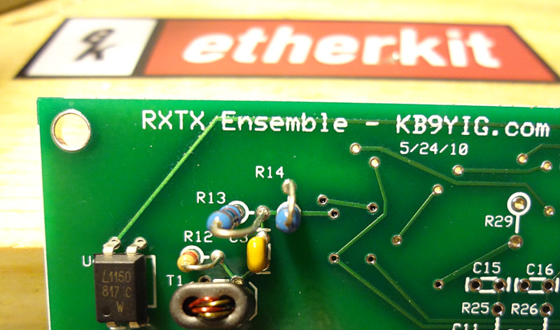
On to the dividers stage of the build. Only 4 components here: a 74AC74 dual flip flop, a SMD cap and two resistors. The pin spacing on the 74AC74 is relatively wide, so it’s pretty easy to solder. The blob and wick method will work, but it’s also pretty easy to do each pin individually. Just have to make sure you get the orientation correct.
Top and bottom of the divider section of the build.
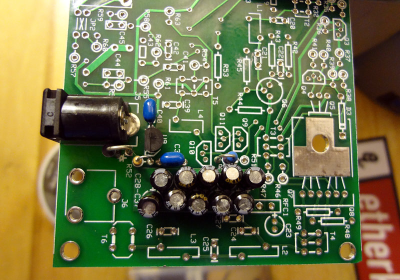
Here’s the top and bottom of the whole board so far.

Next up is the RF I/O and Switching stage. Lots of stuff in that stage including a bunch of toroids and transformers, so that will probably take me a couple of days to do.