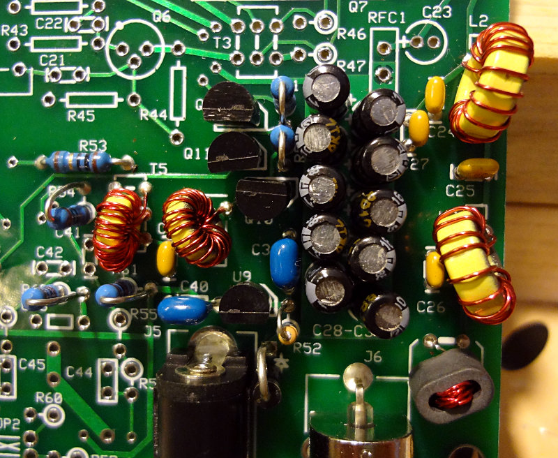
Lots of parts to solder on in the TX op amp section, but most of them are through hole. No band specific compnents to worry about.
You might be tempted to place them all at once and then start soldering, but with all the dangling leads you end up with, it can make getting around with the solder and soldering iron a bit difficult. I found it easier to place a few components, solder, trim the leads and then repeat with a few more components.
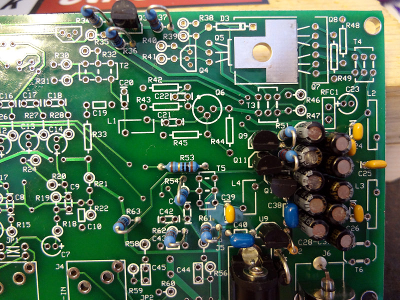
I cross-wired JP1 here instead of jumpering them straight across, based on the notes in the build instructions. May end up having to change this, but we’ll see.

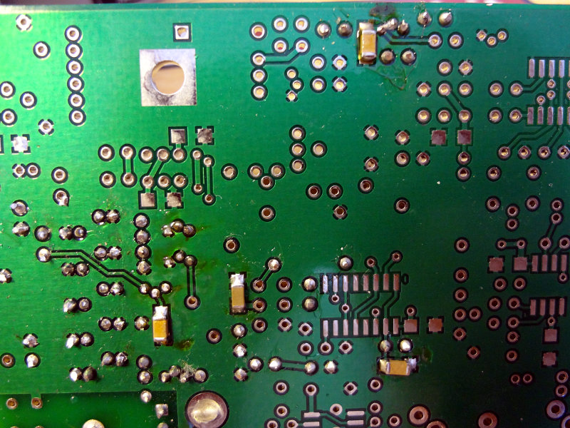
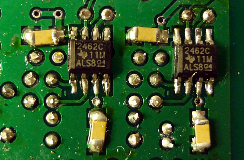
Two SMD op amps and accompanying capacitors go on the bottom of the board. By now, soldering the SMD components should be pretty easy, even if you’re new at working with them.
Getting near the end of the build now. Only two more sections left: the TX mixer and PA. TX mixer section is up next.