Circuit experiment: Colpitts oscillator

To continue debugging my problems with CC1, I needed a signal source that I could feed into the transciever. Jason/NT7S sketched out a simple crystal based Colpitts oscillator circuit for me to try.

Colpitts oscillator schematic

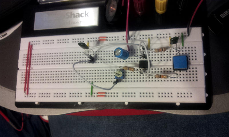
Fortunately I was able to find everything I needed in my parts bin to breadboard the circuit. I used a 7.030 MHz crystal and a 10 pF capacitor at the output.

Colpitts oscillator
Colpitts oscillator
Colpitts oscillator
Colpitts oscillator

Will give it another examination tomorrow to make sure I have all the right components and that everything is laid out properly on the breadboard, then give it some power and see if I get anything out of it.

Adventures in electronics

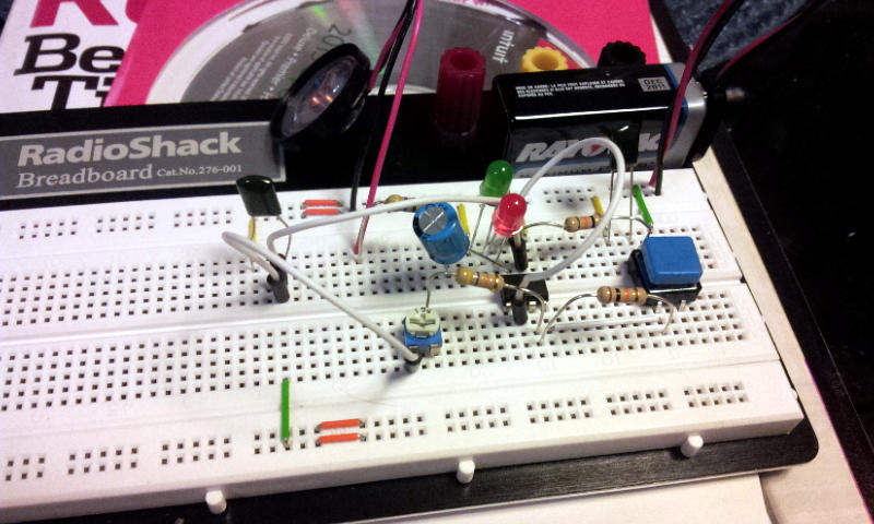
Finally found some time to sit down with all the bits and assemble a second Morse code key using the supplied schematic. At first it didn’t seem to work, but after checking through everything I found one of the speaker wires wasn’t fully inserted (short lead). After I fixed that, it buzzed at me when I clicked the button! The button is the clicky kind, so it’s not that well suited for doing Morse code, but it works! The buzzer was also a lot louder than the kit, which I later discovered was due to me forgetting a resistor between the final capacitor and speaker.

The next step was to make it light up in addition to buzzing. Spent some time looking at the schematic for a place to insert an LED that I didn’t think would make it go poof or fry anything. Put in a red LED and connected it to ground, pushed the button and it lit up! Then I decided to try a second green LED in series with the red, and they both lit up! Success!

A variable resistor instead of the fixed resistor in front of the speaker I think should give me some volume control, so I’ll try that next. I need to get one first.