SA602/SA604 soldering practice

After getting a bit of advice from some locals about soldering, I thought I’d get in a little more practice with the SA602s and the breakout boards. It was also a good excuse to see how my new glasses are for working at the bench.

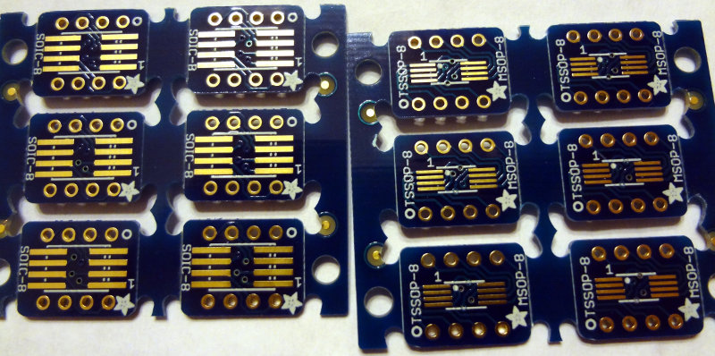
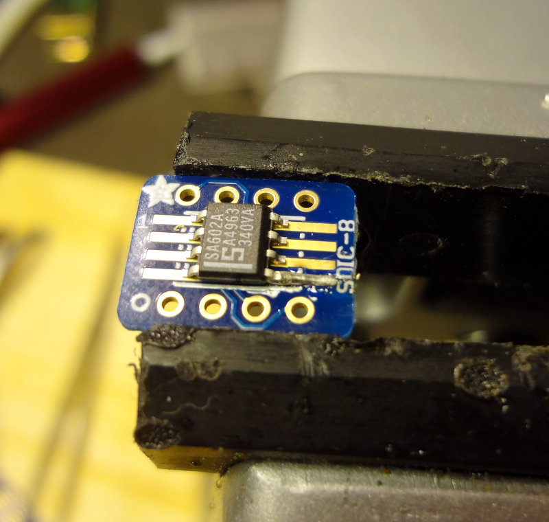
To get a little more room to work, I switched to a conical tip on the soldering iron and soldered the board onto the header pins first. This makes for a pretty stable platform to work on.

Adding header pins
Adding header pins
Adding header pins
Adding header pins

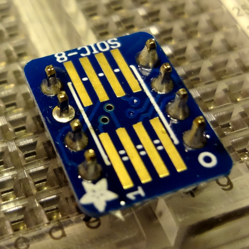
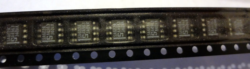
Add a little bit of flux paste, tin one of the pads and then tack on the SA602 to the tinned pad.

SA602 tacked on
SA602 tacked on

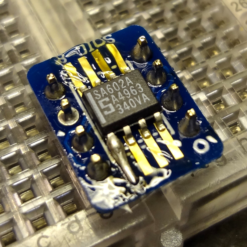
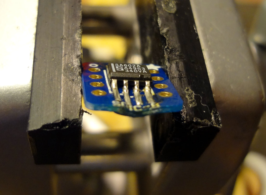
Then flip it around and solder a pin on the other side.

Two pins soldered
Two pins soldered

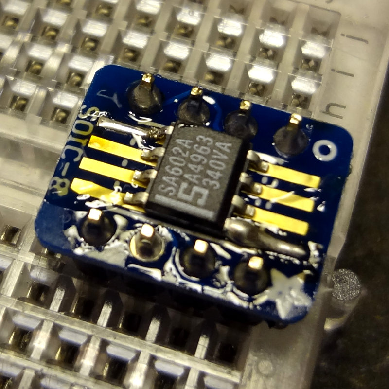
Then solder the rest of the pins, making sure not to leave the soldering iron on the board too long, and waiting a few seconds between soldering each leg to let things cool down a bit. A method that I found worked pretty well was to place the soldering iron tip on the pad, apply a touch of solder to the tip, push it towards the pin, and then draw the tip back along the pad.

SA602 soldered on
SA602 soldered on

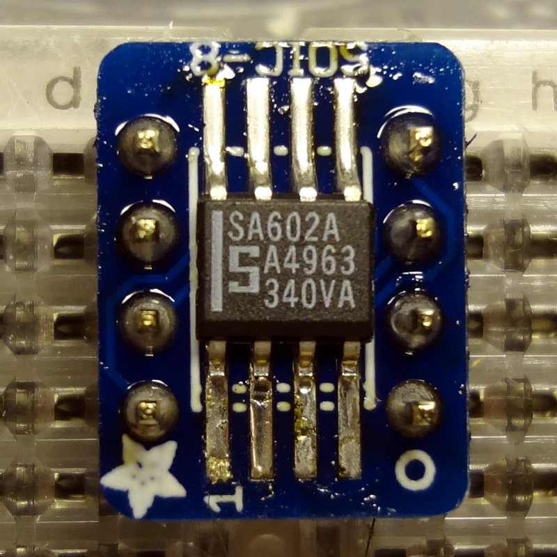
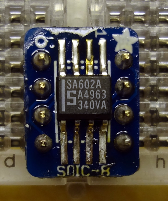
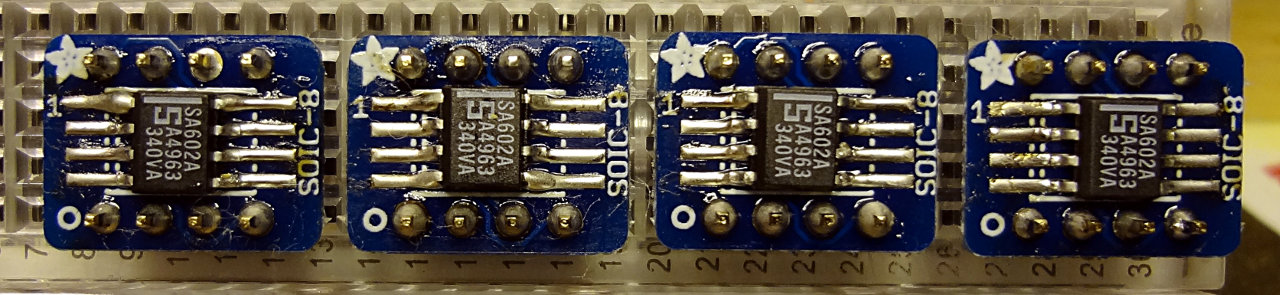
I soldered a total of 4 SA602s onto the breakout boards. Here’s the result of about an hour’s worth of practicing.

4 SA602s on breakout boards ready for experimenting

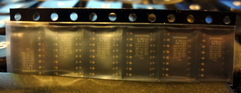
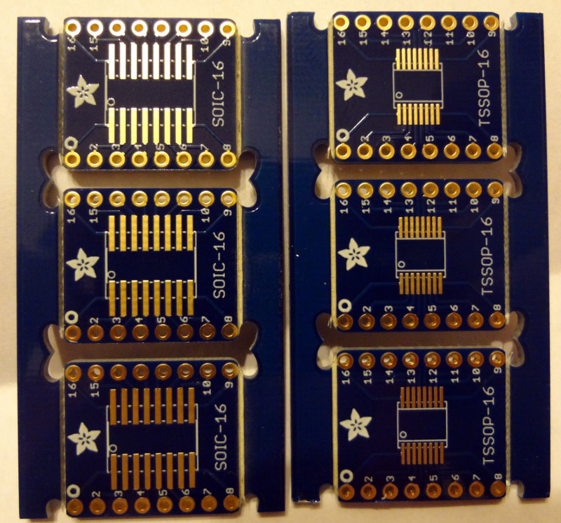
Using the same method, I soldered one of the SA604 chips onto the SOIC-16 breakout board. Although the SA604 is about the same width as the SA602, just longer, the SOIC-16 board is quite a bit larger than the SOIC-8 board. Having the header pins on the same side as the pads gives you a little less room to work with as well. Still, soldering the SA604 was pretty easy.

SA604 soldered onto a breakout board

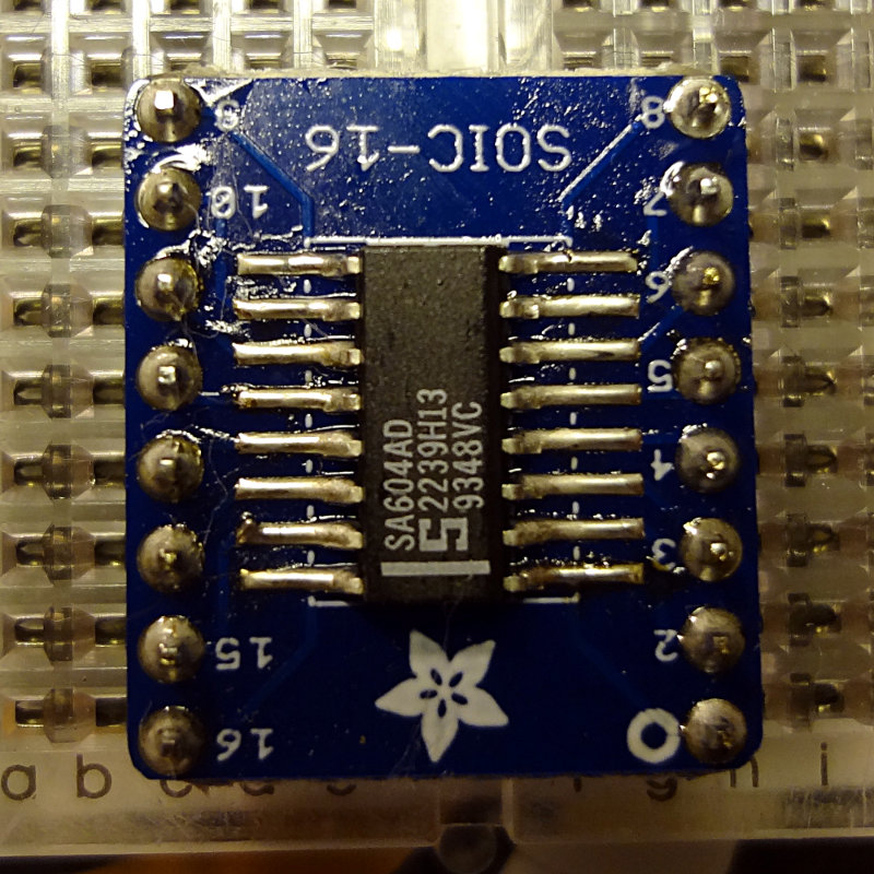
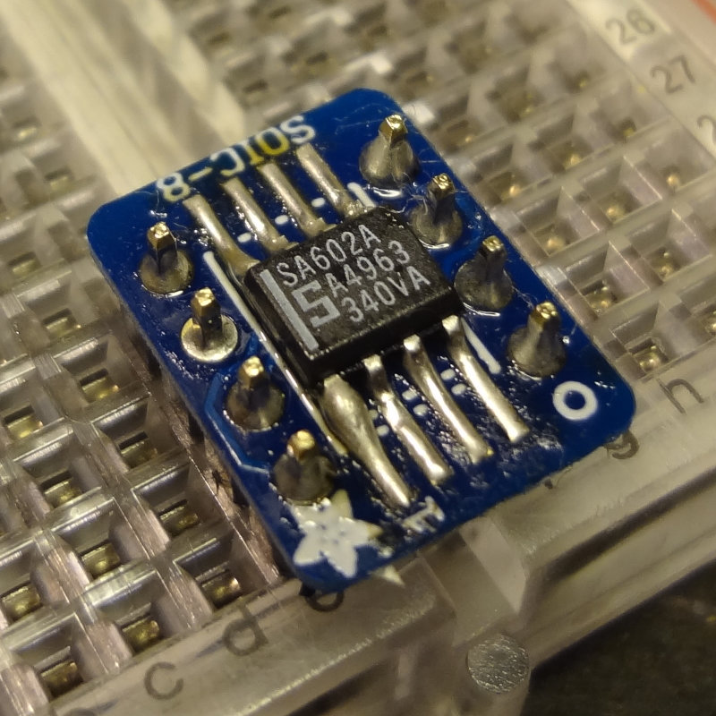
My attempts at cleaning off some of the residual flux left some cotton fibers behind from the swab I was using. I don’t think it will affect how these work, but I’ll spend some time trying to clean them off.

I think I’m getting the hang of this now. Next, learn how to use these.

SA602 and SA604 to play with

Last week, Dave/AA7EE announced that he had a bunch of SA602s and SA604s to give away. I emailed Dave to ask for some, and he sent me 18 602s and 6 604s. Thanks Dave!

These are surface mount ICs, so I ordered up some SOIC-8 and SOIC-16 breakout boards from Adafruit.

The package from Dave arrived earlier this week, and the breakout boards arrived in the mail today.

SA602 SMDs
SA602 SMDs
SA604 SMDs
SA604 SMDs

The breakout boards came bubble-shrink wrapped which was a little unexpected. I thought they’d just come loose in a ziplock bag or something.

Adafruit SMD breakout boards

The boards are double sided, with SOIC-8/16 spacing on one side and TSSOP-8/16 spacing on the other side.

Adafruit SOIC/TSSOP 8 breakout boards
Adafruit SOIC/TSSOP 16 breakout boards

Interestingly enough, the SOIC-8 boards are half the thickness of the SOIC-16 boards, which are a regular thickness circuit board. Both have sets of holes (standard 0.1″ spacing) to solder header pins to, making them convenient to use in breadboard projects. Or you could just solder wires to them if that’s what the project calls for.

Off to the workbench to do some soldering. For SMD parts, these are actually pretty large, and soldering is relatively easy. First, tin one of the pads and then with tweezers, line up the IC and then heat up the tinned pad. Use the soldering iron to push the solder towards the IC pin and you’re done.

Soldering an SA602 to the breakout board

I used a toothpick to apply a little bit of flux paste to the rest of the pads, and then soldered the rest of the pins. That part goes pretty easily with flux.

Pro tip #1: Don’t do this with the board clamped in a vise, or if you do, don’t leave the soldering iron on the board for too long. These SOIC-8 breakout boards are pretty thin and too much heat will make them melty. Oops.

Melted breakout board. Ooops

Once you’re done, it’s time to add some header pins. This part is easy. Stick the header pins into a breadboard, put the breakout board on the header pins and solder.

Adding header pins
Adding header pins

Pro tip #2: In your enthusiasm to solder, don’t forget to pay attention to where Pin 1 of the IC is supposed to go (ignore that bad solder job on Pin 2…easy to fix). That stripe on the SA602 should be where the 1 is printed on the board. Oops.

SA602 is upside down on the breakout board. Ooops

Code practice oscillator completed

The panel mount potentiometer I used in the CPO was missing the nut needed to secure it into place. After determining that I needed a 1/4″-32 thread hex nut, I went scouring my Radio Shack and hardware store bins looking for some.

At Radio Shack, I found a bag of assorted hex nuts in their parts bins, with the right thread number, but none of them were smaller than 5/16″. Next stop was a big box hardware store. There I found 1/4″ nuts, but the finest thread they had was 28. The hex nuts they did have with a 32 thread were all #10 or smaller.

Then I went to a couple of the smaller box hardware stores. Much larger selection of nuts and bolts, but still the same problem as with the big box hardware store. Nothing with a finer thread than 1/4″-28, and nothing larger than a #10-32.

So much for instant gratification.

Thanks to a suggestion in the Google+ Ham Radio Homebrew community, I found some (Bourns H-38-1) at Mouser Electronics. Ordered 20 of them so I’d have extras in case I needed some for later. They arrived a few days ago and now my NT7S code practice oscillator is complete!

NT7S code practice oscillator

Code practice oscillator enclosure

The mini-breadboard version of the NT7S code practice oscillator along with 9V battery fits perfectly into an Altoids tin (the preferred enclosure of tinkerers everywhere). This evening I spent some time wiring up the board to the jacks and power switch.

When I plugged in the headphones and my straight key, I was greeted with a continuous tone, and nothing happened when I tapped the key. Crap, I must have a short somewhere. After a bit of looking around on the board, I went back into the house to grab the schematic, and then realized I had plugged things into the wrong jacks. Swapped the headphones and key and got nice sounding tones when I tapped the key, just as expected. Works great and everything sits in the tin nice and securely. The battery slides around a tiny bit, but that’s not a big deal.

NT7S code practice oscillator in an enclosure

Now I can bundle up my straight key and some headphones and practice wherever I want.

Mini code practice oscillator

I’ve been wanting something small and portable that I could carry around with me for doing Morse Code practice. The Heathkit HD-10 oscillator is fun to play with, but kind of big and chunky to haul around. The ARRL code oscillator is small and portable, but the buzzing sound gets kind of unpleasant to listen to after a while.

Then I found Jason’s/NT7S schematics for his code practice oscillator (CPO) in his blog and decided to build one. I gathered up the pieces and tried to assemble it on a breadboard a while ago but got distracted by other things and never quite finished.

With the acquisition of some solderable mini-breadboards from SparkFun and the perma-protoboards from Adafruit, it was time to get back to the project. The Sparkfun mini breadboard fits perfectly on top of one of their modular mini breadboards so I put the solderable breadboard on top of the modular breadboard and started laying out the components. Then, once I’m done all I have to do is carefully lift the solderable breadboard off the modular breadboard and then solder away.

After spending some time staring at the schematic and the breadboard pondering how to lay things out, I remembered a suggestion from the kit building forum at the ARRL Centennial Convention. Build modularly and test as you go so that if something doesn’t work, it’s easier to isolate the problem area.

With this in mind, I started with the power section of the schematic and laid that out in one corner of the board. Add power, flip the switch, LED comes on. Perfect!

The CPO is small and simple enough so that the rest of the circuit pretty much falls into place after that. After a few hours of placing components, double checking placement and debugging, I finally managed to get it working.

NT7S Mini-CPO
NT7S Mini-CPO
NT7S Mini CPO
NT7S Mini CPO

With a few wires, I connected my straight key and connected straight to the plug of some ear buds I had lying around. Tapping on the key yielded some pleasant sounding tones, and turning the pot changed the volume (and frequency a tiny bit).

NT7S Mini CPO connected to the straight key

Now all I need to do is solder everything into place, add some jacks and stick it into an enclosure.

A nice, easy build and I was able to do it all with parts I had on hand.