Another Si5351A board

A few days ago, Jason/NT7S announced the Etherkit Si5351A breakout board was getting an upgraded TCXO oscillator with improved performance. I’ve already got a few of them waiting for me to put to work, so why not add another one.

Unlike the previous boards I bought (from the crowdfunding campaign), the latest versions now come fully assembled except for the header pins. If the thought of soldering tiny surface mount devices was keeping you from trying the breakout board, worry no more.

The 10 mW WSPR beacon app note looks pretty interesting, and I think it would be fun to try to get one set up once we’re in the new house. I’d love to see how far it could be heard.

We’ll hopefully be in the new house in a few more weeks. I’m looking forward to getting the shack and workshop set up again so I can get to playing.
Si5351 on the oscilloscope

The Si5351 breakout boards all work, at least according to the frequency counter, so I thought I’d put the oscilloscope on one to see what was coming out. I just connected the output of the Si5351 board straight to the oscilloscope using an SMA/BNC pigtail. I’m sure it’s a totally incorrect way of doing it, but all I wanted to see was if I got a waveform and if it changed when I changed the Si5351 frequency.

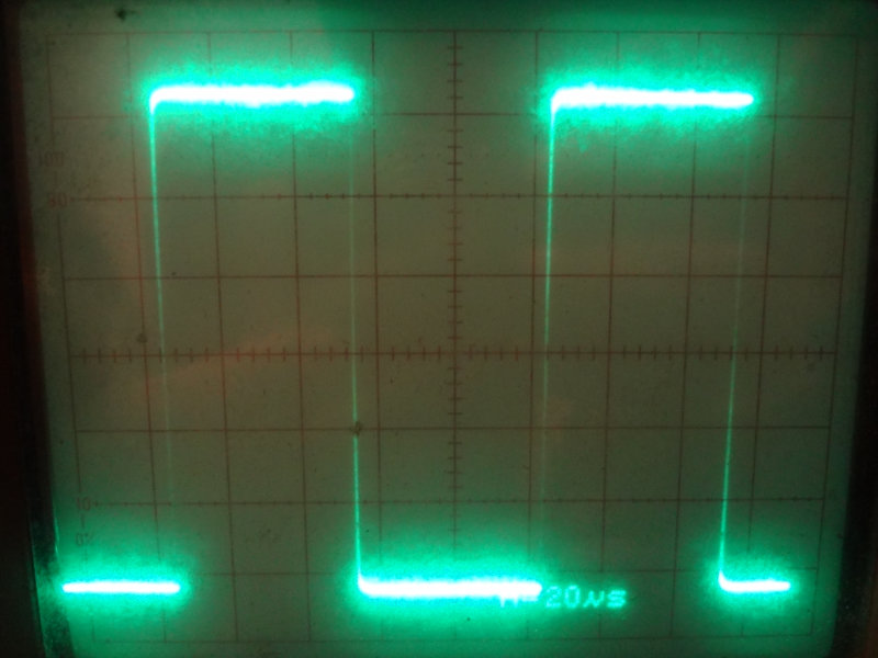
I’ve been told that the Si5351 output is a square wave, and at kHz frequencies, that’s what I get. This is the 10 kHz waveform. Nice looking square waves.

Etherkit Si5351 10 kHz waveform on the oscilloscope

Going up a few orders of magnitude to 1MHz, the shape of the waveform loses its squareness, most likely due to the way I’ve connected things (impedance mismatch, improper loading and all that). But, as the time base shows, it’s a much higher frequency signal.

1MHz wave form
1MHz wave form

At 10 MHz, there’s even more distortion of the waveform, but definitely higher frequency.

10MHz waveform
10MHz waveform

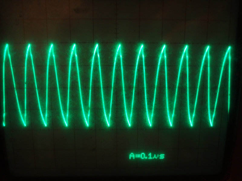
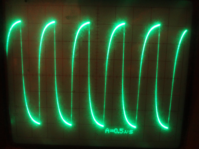
Up at 20MHz, things are looking pretty triangular.

20MHz wave form
20MHz wave form

So, TIL:

  • My Si5351 board really works! Yay!
  • You can’t just connect things willy-nilly to an oscilloscope and expect good results. (I already knew this, just wasn’t important for this purpose.)
  • There are still some things I need to learn about using this particular oscilloscope.

Si5351 breakout board

Jason/NT7S launched the crowdfunding campaign for his version of an Si5351 breakout board last night, and already this morning it’s at over 150%. The stretch goal at $1 500 involves spending some more time on the software library to make the board easier to use.

It’s a neat little oscillator chip that seems to provide a lot of capabilities for not a lot of money. He’s been documenting his investigations on the chip at his blog for the past year now, including building a couple of receivers and transceivers around the Si5351.

The Si5351A is quite a capable IC at a very modest price. It is a PLL clock generator with three independent outputs which can each generate a separate signal from 8 kHz to 160 MHz. A 25 or 27 MHz reference oscillator is used for the two internal PLLs (the Etherkit breakout board uses a 25 MHz reference oscillator), which allows the user to choose the amount of frequency stability and accuracy required.

Go check out the Si5351 breakout board campaign on Indiegogo, and pick one up if it’s something you’ll find useful in an upcoming project.

1N34A diodes

One of the projects I’ve been considering for a while is trying my hand at building some crystal radio receivers. Crystal radios are pretty simple and traditionally use a germanium diode as the detector element because of its low forward voltage drop.

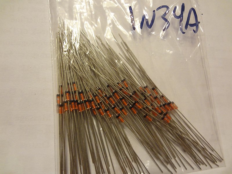
Found several people selling 1N34A germanium diodes on eBay and ordered a batch of 100 a couple of weeks ago. They arrived in the mail yesterday, and today I got around to checking them out. The diodes themselves are unlabeled so there’s really no way to tell what they are by looking at them.

Bag of 1N34A diodes
Bag of 1N34A diodes

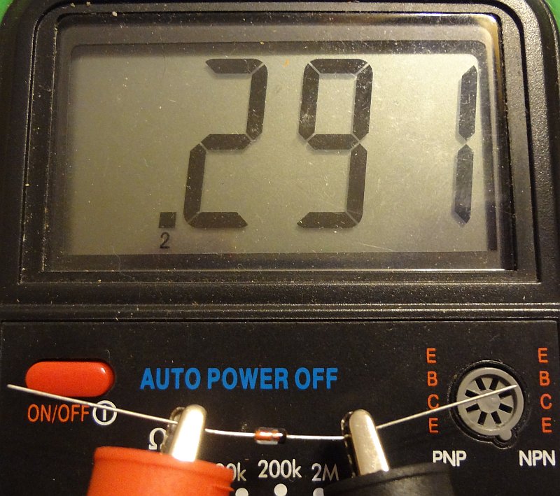
The forward voltage (Vf) drop of 1N34A diodes is supposed to be around 0.25V. According to my DMM, a random sampling of the ones I got showed a Vf of 0.29-0.30V. I figure that’s pretty close.

Measuring forward voltage drop of the diode

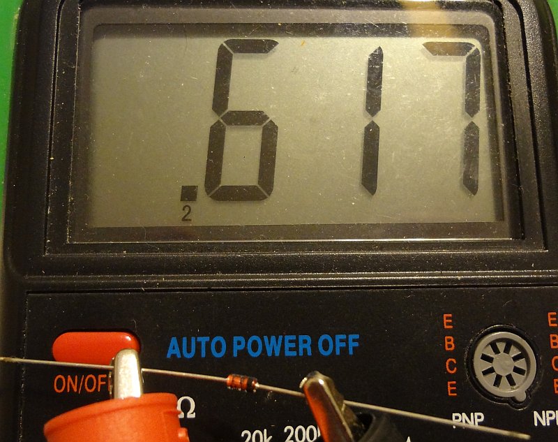
For comparison, the Vf of some random 1N4148 silicon diodes was around 0.6V.

1N4148 forward voltage drop

Now to do some homework and see how to go about building a crystal radio receiver.

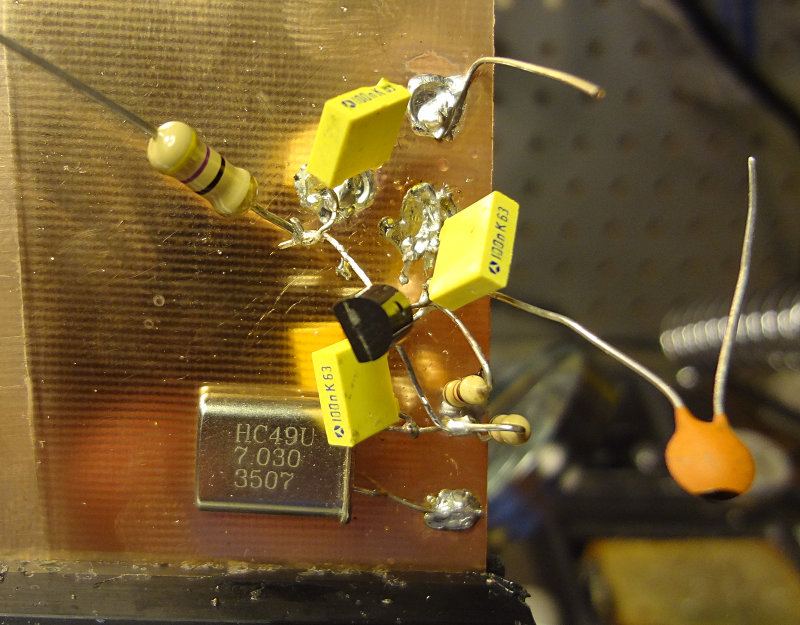
Ugly construction attempt

My first attempt at building a circuit using the ugly construction technique. It’s supposed to be a simple oscillator circuit using a J310 transistor.

One of the advantages of ugly construction is that if you’re working from a schematic or circuit drawing, building is pretty easy. I found that soldering components to the copper clad required a bit of patience, because it’s essentially a very large heat sink. Put the soldering iron on the copper clad, add solder until you get a good sized pool, leave the soldering iron in place and place the component.

For this particular circuit, Vcc is applied to the big resistor with the free lead and output is off the capacitor with the free lead. I soldered on a piece of wire to make the ground connection easier. Haven’t applied power to test it out yet. Will see if it works later on.