Another battery charger dissection

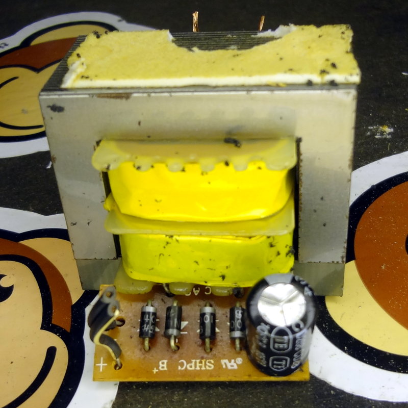
The final wall wart dissection (for now) is a dead charger for the battery of a 14V cordless drill. Rated at 18VDC out, this one is just a wall wart that plugs directly into the battery.

Cordless drill charger

Like the previous wall wart, it consists of a large transformer with a simple full wave rectifier circuit. The rectifier circuit on this wall wart is attached right at the secondary of the transformer and adds a capacitor across the rectifier output to smooth out the ripple from the rectifier.

With this one, there appeared to be no continuity on either the primary or secondary side which certainly explains the 0V my DMM was giving me at the plug.
Battery charger innards

Today’s dissection was a dead battery charger for an 18V Black and Decker FireStorm battery that goes into my sander. The charger died a few years back and I came across it while cleaning out the junk box. The label says it takes 120V AC output and puts out 21.75V DC output. Putting the DMM across the terminals only gave about 3.8VDC.

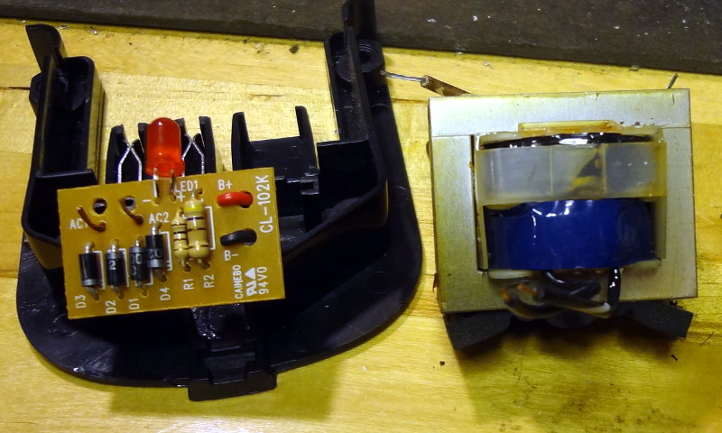
Battery charger guts

Inside the part that plugs into the wall is a large transformer (right), like the previous wall wart. At the other end is the part that clips onto the battery. Inside I found a simple circuit with some diodes, resistors and an LED to indicate charging. Any time I see 4 diodes, I think “rectifier”, so I drew out the circuit based on the circuit board traces. Sure enough, I found a full wave bridge rectifier.

Checking the transformer, there was no continuity on the primary side, but the secondary side was fine. Made me wonder how I was getting the 3.8V at the charger terminals.

Based on this, I have a feeling the innards of the next wall wart on the dissection tableworkbench is going to be similar: big transformer with some rectifying circuitry to produce a “DC” output.

Wall wart anatomy

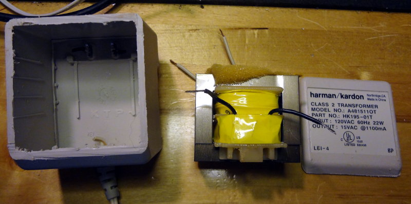
Some wall warts, as it turns out, are pretty simple inside. This dead one from an old set of speakers, is just one big transformer inside that case. According to the label, it just takes 120VAC and transforms it down to 15VAC.

Wall wart guts
Wall wart guts

The primary side of the transformer measures fine with continuity between the two leads. On the secondary side though, my DMM gives me about 50Ω resistance between the two leads. I’m guessing that’s probably why it was discarded as dead.

It will be interesting to see what an AC->DC wall wart looks like inside.

From breadboard to Perma-Proto board

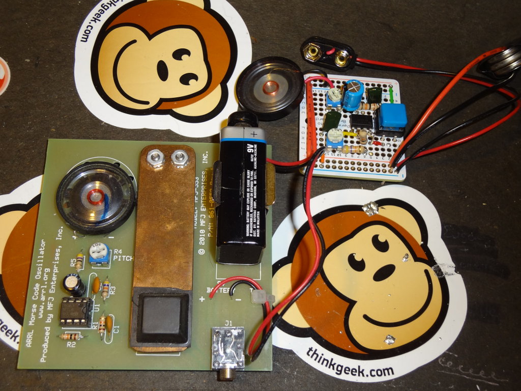
First I took the little Morse code kit and put it onto a breadboard. Over at adafruit.com, they have these neat Perma-Proto PCBs that are circuit board versions of a breadboard. Makes it easy to transfer something you’ve assembled on a breadboard to something a little more permanent.

I picked up a few a little while ago with the intention of transferring the breadboard version of the  Morse code kit to a Perma-Proto board and finally got around to it this evening.

Morse code practice oscillator

A nice relaxing couple of hours spent melting some solder.

Power supply!

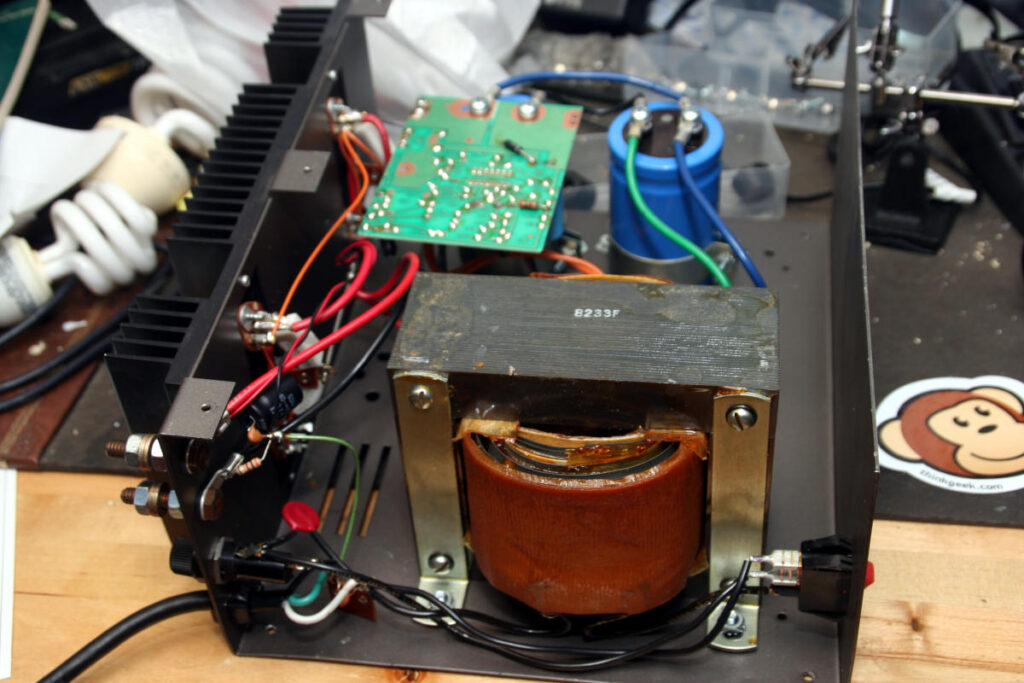
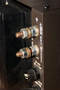
An Astron RS-35A power supply is my latest acquisition. Saw it on ebay for a pretty decent price, and after a few days of watching it, I thought I’d put a bid on it fully expecting someone to come in at the last minute and snipe me.

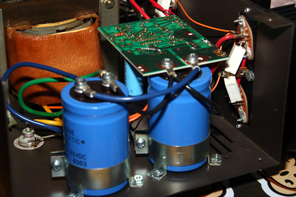
Well, that didn’t happen so now I have a big beast of a linear power supply that puts out 13.7V and peak current of 35A (“25A continuous”) for less than half of what one costs new. My original plan was to use it for what ever radio I ended up buying, but we’ll be putting Connie’s radio and its power supply into the office/ham shack so this one will probably sit out on the workbench and supply power to my other projects, maybe a second radio if we end up getting one.

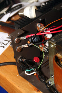
Except for a dinged up corner and a broken foot (probably during transport) it’s physically in good shape. After plugging the unit in, flipping the power switch brings the beast to life with an intimidating but satisfying “chunk” from the transformer and the hum of electricity.

The power terminals are these bare exposed bolts with nuts to hold any wires on. I don’t really like the thought of exposed power terminals, so I think I’ll look into replacing them with some Anderson power poles.