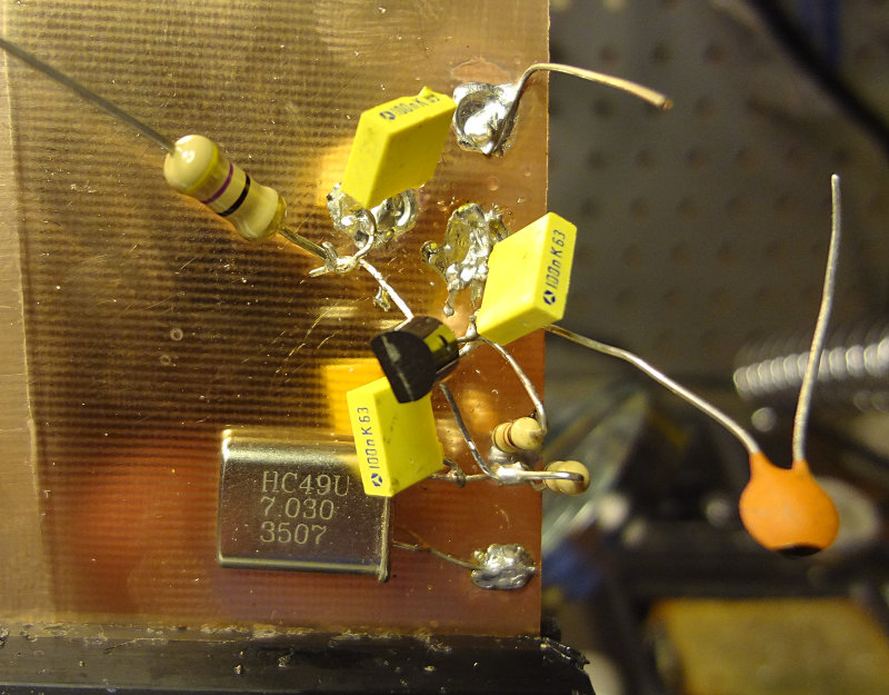
My first attempt at building a circuit using the ugly construction technique. It’s supposed to be a simple oscillator circuit using a J310 transistor.
One of the advantages of ugly construction is that if you’re working from a schematic or circuit drawing, building is pretty easy. I found that soldering components to the copper clad required a bit of patience, because it’s essentially a very large heat sink. Put the soldering iron on the copper clad, add solder until you get a good sized pool, leave the soldering iron in place and place the component.
For this particular circuit, Vcc is applied to the big resistor with the free lead and output is off the capacitor with the free lead. I soldered on a piece of wire to make the ground connection easier. Haven’t applied power to test it out yet. Will see if it works later on.
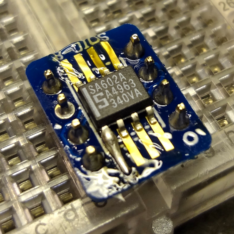
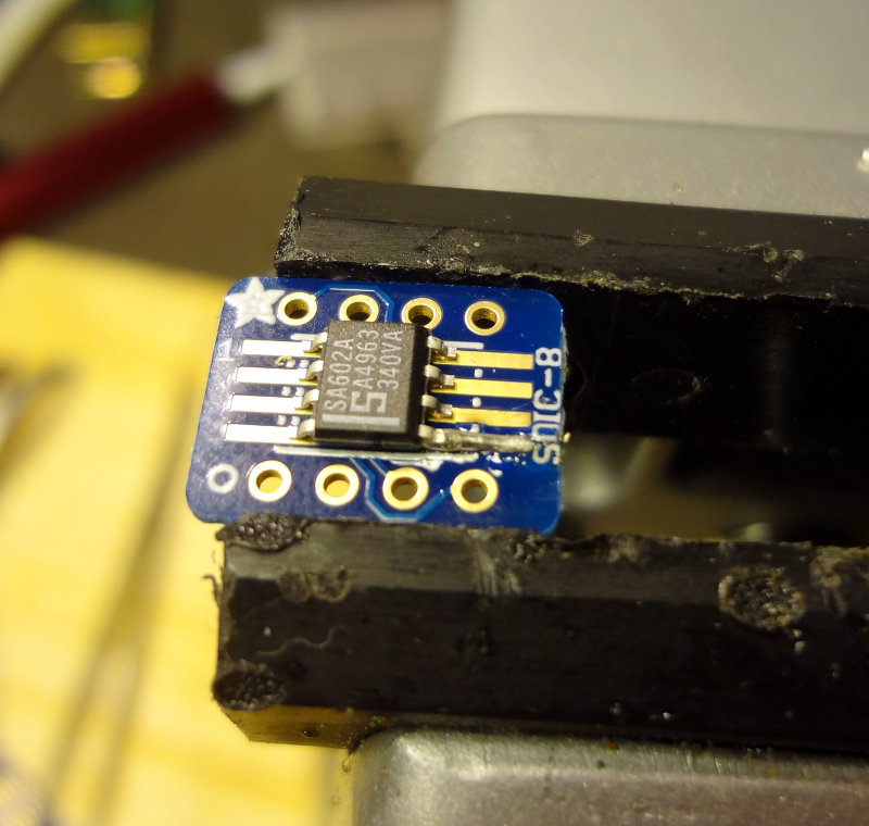
After getting a bit of advice from some locals about soldering, I thought I’d get in a little more practice with the SA602s and the breakout boards. It was also a good excuse to see how my new glasses are for working at the bench.
To get a little more room to work, I switched to a conical tip on the soldering iron and soldered the board onto the header pins first. This makes for a pretty stable platform to work on.
Adding header pins
Adding header pins
Add a little bit of flux paste, tin one of the pads and then tack on the SA602 to the tinned pad.
SA602 tacked on
Then flip it around and solder a pin on the other side.
Two pins soldered
Then solder the rest of the pins, making sure not to leave the soldering iron on the board too long, and waiting a few seconds between soldering each leg to let things cool down a bit. A method that I found worked pretty well was to place the soldering iron tip on the pad, apply a touch of solder to the tip, push it towards the pin, and then draw the tip back along the pad.
SA602 soldered on
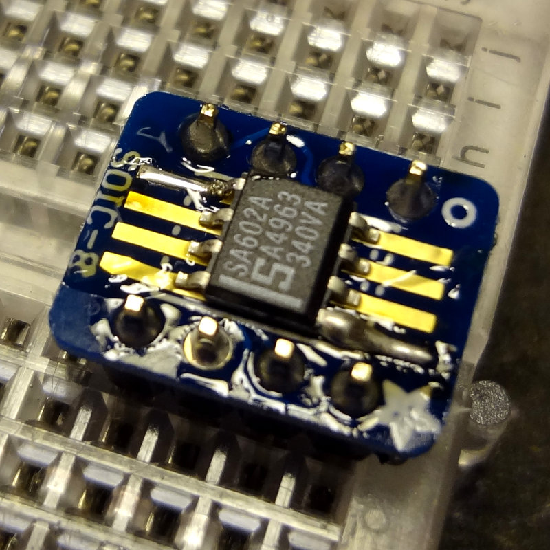
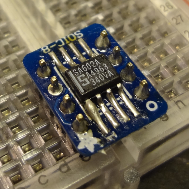
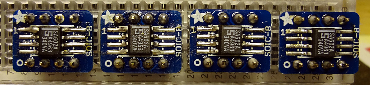
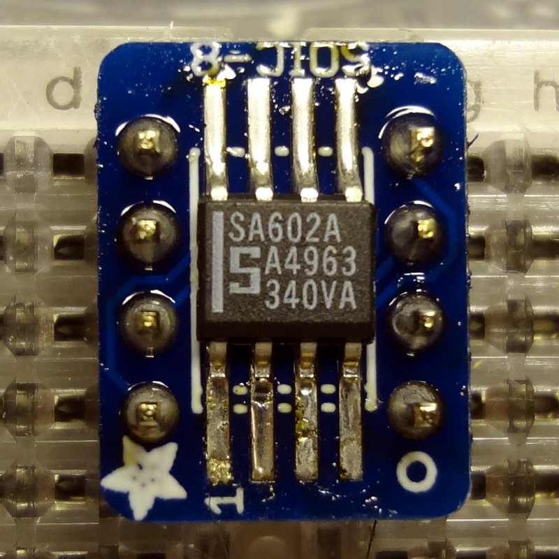
I soldered a total of 4 SA602s onto the breakout boards. Here’s the result of about an hour’s worth of practicing.
4 SA602s on breakout boards ready for experimenting
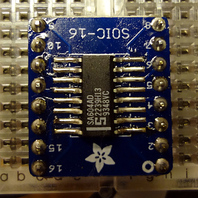
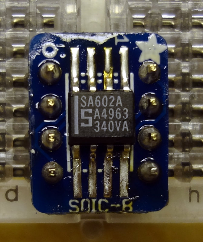
Using the same method, I soldered one of the SA604 chips onto the SOIC-16 breakout board. Although the SA604 is about the same width as the SA602, just longer, the SOIC-16 board is quite a bit larger than the SOIC-8 board. Having the header pins on the same side as the pads gives you a little less room to work with as well. Still, soldering the SA604 was pretty easy.
SA604 soldered onto a breakout board
My attempts at cleaning off some of the residual flux left some cotton fibers behind from the swab I was using. I don’t think it will affect how these work, but I’ll spend some time trying to clean them off.
I think I’m getting the hang of this now. Next, learn how to use these.
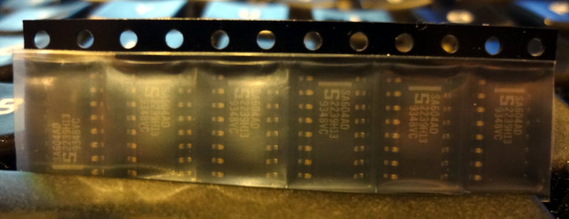
Last week, Dave/AA7EE announced that he had a bunch of SA602s and SA604s to give away. I emailed Dave to ask for some, and he sent me 18 602s and 6 604s. Thanks Dave!
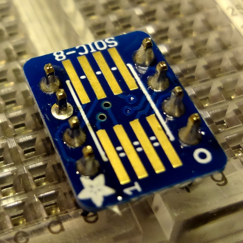
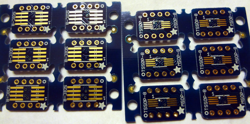
These are surface mount ICs, so I ordered up some SOIC-8 and SOIC-16 breakout boards from Adafruit.
The package from Dave arrived earlier this week, and the breakout boards arrived in the mail today.
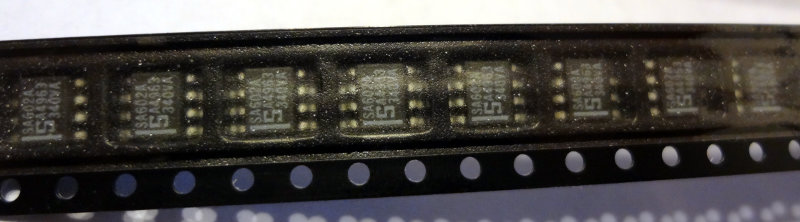
SA602 SMDs
SA604 SMDs
The breakout boards came bubble-shrink wrapped which was a little unexpected. I thought they’d just come loose in a ziplock bag or something.
Adafruit SMD breakout boards
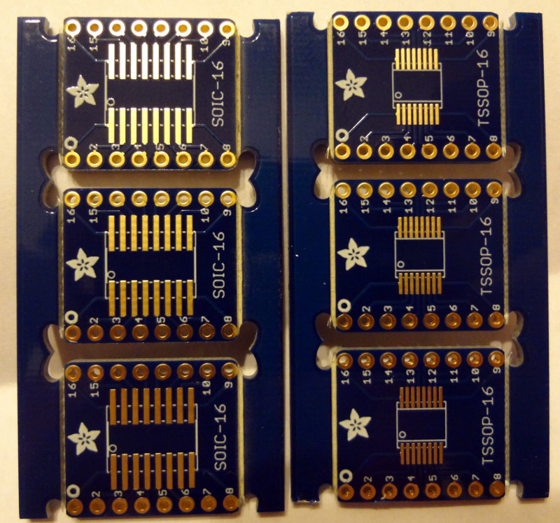
The boards are double sided, with SOIC-8/16 spacing on one side and TSSOP-8/16 spacing on the other side.
Adafruit SOIC/TSSOP 8 breakout boards
Adafruit SOIC/TSSOP 16 breakout boards
Interestingly enough, the SOIC-8 boards are half the thickness of the SOIC-16 boards, which are a regular thickness circuit board. Both have sets of holes (standard 0.1″ spacing) to solder header pins to, making them convenient to use in breadboard projects. Or you could just solder wires to them if that’s what the project calls for.
Off to the workbench to do some soldering. For SMD parts, these are actually pretty large, and soldering is relatively easy. First, tin one of the pads and then with tweezers, line up the IC and then heat up the tinned pad. Use the soldering iron to push the solder towards the IC pin and you’re done.
Soldering an SA602 to the breakout board
I used a toothpick to apply a little bit of flux paste to the rest of the pads, and then soldered the rest of the pins. That part goes pretty easily with flux.
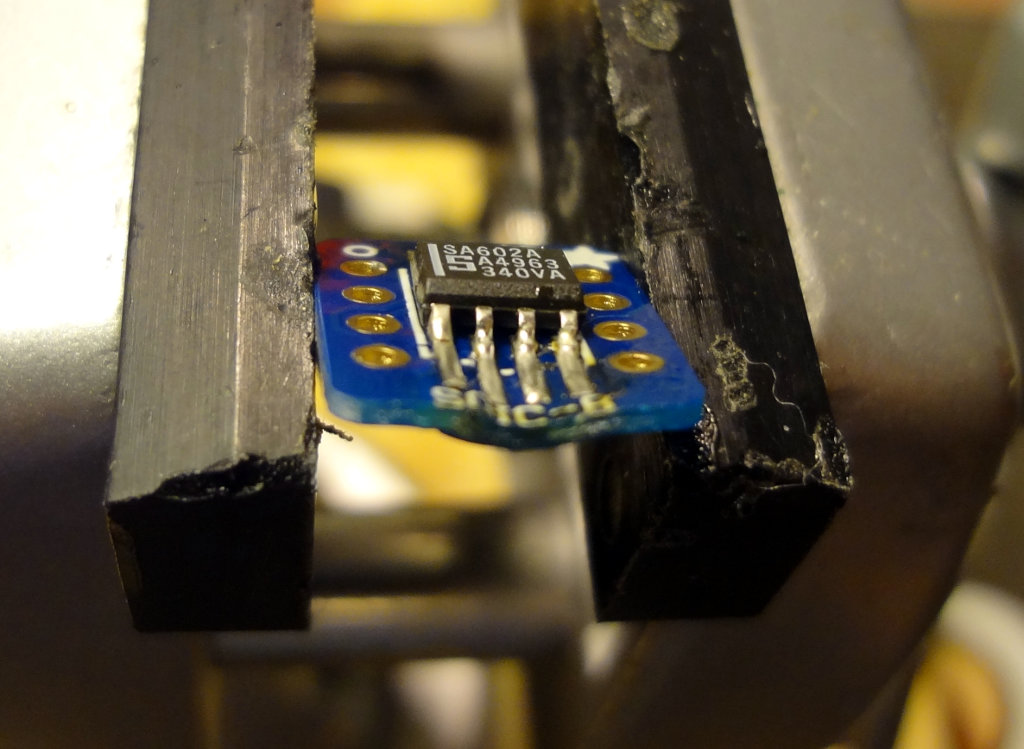
Pro tip #1: Don’t do this with the board clamped in a vise, or if you do, don’t leave the soldering iron on the board for too long. These SOIC-8 breakout boards are pretty thin and too much heat will make them melty. Oops.
Melted breakout board. Ooops
Once you’re done, it’s time to add some header pins. This part is easy. Stick the header pins into a breadboard, put the breakout board on the header pins and solder.
Adding header pins
Pro tip #2: In your enthusiasm to solder, don’t forget to pay attention to where Pin 1 of the IC is supposed to go (ignore that bad solder job on Pin 2…easy to fix). That stripe on the SA602 should be where the 1 is printed on the board. Oops.
Got the log check results from CQ WPX 2014 in my email today. Out of my 77 QSOs, 4 of them got busted (1 incorrect call, 3 incorrect exchanges) leaving me with 73 QSOs and a score of 13510. On the other side, 3 stations copied my exchange incorrectly. Not as good compared to last year’s CQ WPX. I’ll just have to keep at it to get better, right?
************************** Summary ***************************

      77 Claimed QSO before checking (does not include duplicates)
      73 Final   QSO after  checking reductions

     202 Claimed QSO points
     193 Final   QSO points

      73 Claimed mults
      70 Final   mults

   14746 Claimed score
   13510 Final   score
   -8.4% Score reduction

    5.2% Error Rate based on claimed and final qso counts
       0 (0.0%) duplicates (without penalty)
       1 (1.3%) calls copied incorrectly
       3 (3.9%) exchanges copied incorrectly
       0 (0.0%) not in log
       0 (0.0%) calls unique to this log only (not removed)

********************** Results By Band ***********************

            Band   QSO   QPts  Mult

   Claimed  160M     0      0
   Final    160M     0      0

   Claimed   80M     0      0
   Final     80M     0      0

   Claimed   40M     4      4
   Final     40M     4      4

   Claimed   20M     2      6
   Final     20M     2      6

   Claimed   15M     5     11
   Final     15M     3      7

   Claimed   10M    66    181
   Final     10M    64    176

  Claimed    All    77    202    73  Score    14746
  Final      All    73    193    70  Score    13510

*********************** Incorrect call ***********************

28625 PH 2014-03-30 1826 AB4UG           18 NY6Y          1623 correct     NY6N

*************** Incorrect Exchange Information ***************

21447 PH 2014-03-29 1748 AB4UG            1 NE5D          0034 correct  934
28581 PH 2014-03-30 1920 AB4UG           48 9A73P         5718 correct 5708
21235 PH 2014-03-30 2118 AB4UG           70 US5D          3354 correct 2354

********************** Lost Multipliers **********************

21447 PH 2014-03-29 1748 AB4UG            1 NE5D          0034 correct 934
28625 PH 2014-03-30 1826 AB4UG           18 NY6Y          1623 correct NY6N
28581 PH 2014-03-30 1920 AB4UG           48 9A73P         5718 correct 5708

************************ Multipliers *************************

     5E5     8P5     9A5     AD5     CT1
      D4     DA2     DQ8      E7     E77
     EA3     EC1     ED1     ED5     EI7
     EI9      F5      G5     HA1     HA6
     HG1     HG7     HK1      I0     IB9
     II2     II4     II9     IK2     IT9
     IY1     IZ5     J42     KB3     KP4
     LO5     LT7     LZ9      N9     NP2
     OA4     OL4     OT5     PJ2     PW5
     S50     S51     S52     S54     S55
     S57     SN2     SN8     US5     VA5
     VC6     VK4     VP2     WB2     WG3
     WP2     WP4     WX3     XE1     XE2
     YP0     YS1     YT0     YT5     YV4


********* Stations Copying Your Exchange Incorrectly**********

28647 PH 2014-03-29 1810 EC1DBO        1452 AB4UG         0009  should be 5
28000 PH 2014-03-30 1844 US5D          2168 AB4UG          123  should be 23
28340 PH 2014-03-30 2019 YS1YS          987 AB4UG         0051  should be 61
For the circuit platform, copper clad PCB needs to be cut to an appropriate size. A circuit that only takes up 25 cm2 doesn’t need to be built on a 100 cm2 board unless you’re planning for future expansion.
In addition, for Manhattan style, I need some pads. A hole punch or nibbling tool is commonly used to create circular pads out of copper clad PCB. I haven’t acquired any of the MeSquares that Dave/AA7EE prefers yet, nor have I added a hole punch or nibbling tool to the tools on the bench yet. I have a tin snip and a Dremel with some cutting wheels, so off I went to the workbench to experiment with what I had on hand.
Dave/AA7EE posted a nice tutorial describing how he cuts PCB material using a sharp utility knife. That was the first technique I tried.
I took one of the smaller pieces of copper clad PCB from the box I ordered earlier in the year and clamped it to the workbench. Using one of my utility knives, I made 3-4 cuts using a fair bit of pressure on the blade. Then I clamped it in the vise and with a bit of force, was able to break off the piece I had scored. I only scored one side, but it seemed to work pretty well. There were some sharp copper edges on the unscored side, so scoring both sides seems to be the way to go. Cutting through the copper was pretty hard on the blades, and I can see how you could go through a bunch of blades if doing it this way. Blades are pretty inexpensive though. For cutting larger pieces of PCB, this is probably the way to go.
Next were the tin snips, basically big beefy scissors. They cut through the PCB with a little bit of effort, but it’s hard to make longer cuts with them because the tin snips are kind of stubby. For any cuts longer than 3-4 cm, the PCB ended up getting bent out of shape from the snips. I was able to take a strip of PCB (cut using the scoring technique) and use the snips to cut off some island-sized pieces of PCB. For small cuts, the snips worked pretty well. For large cuts, not so much.
Finally it was the Dremel’s turn. With the PCB clamped to the table, the cutting wheel easily scored the PCB, but without a guide cutting a straight line takes a bit of practice. The cutting wheel cut through the PCB material pretty easily too, although the wheel got eaten up pretty quickly in the process. A good bit of dust was created too, so wearing some kind of mask would definitely be in order. I think for cutting or scoring PCBs, I’ll skip the Dremel. Cutting wheels are significantly more expensive than utility knife blades, and copper and fiberglass dust probably isn’t something I want floating around the workshop anyway.
For now, I’ll work on practicing and refining my skills using the scoring method and the tin snips for cutting pads while I save a few dollars to get a decent hole punch. I suspect I’ll end up doing a combination of hole punched and MeSquares for Manhattan islands in the future.