Tracing out a schematic for this power supply has been pretty fun so far. It’s also been a good excuse to learn how to use KiCad.
So far I’ve made it past the rectifier and filtering capacitors up to the power transistors. I’m pretty impressed with the way the innards of this thing are put together. The bridge rectifier part took me a bit to figure out until I realized there were two different stud mount diodes in it.
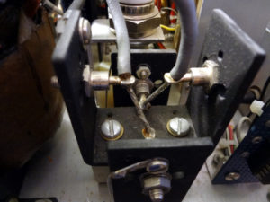
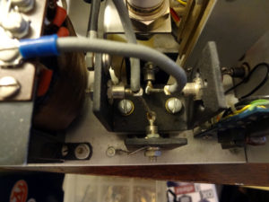
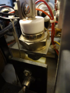
I’ve come across a couple types of components that took me some searching to figure out what they were (still not quite sure what one of them is). This one in particular is one I haven’t been able to identify.
It’s connected to one of the outputs of the bridge rectifier and the control board at the top. At the bottom it’s connected to an air core inductor and parts that lead to the 2N5886 power transistors. A Google search of the numbers printed on it take me to a single page at a store that has it listed as a rectifier diode.
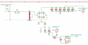
This is the schematic I’ve cobbled together so far. Things start to get a bit confusing after the rectifier, but I think it’s reasonably accurate.
I wasn’t able to find symbols for everything in the KiCad library, particularly for the connectors, so I just used something that looked reasonable.
This has been a fun exercise so far. The power transistor section will probably take me a while to figure out.
Discover more from AB4UG Radioblog
Subscribe to get the latest posts sent to your email.


Mystery component identified. I’m pretty sure it’s a silicon controlled rectifier (SCR) based on a comment on one of my Facebook posts, looking through some other power supply schematics I have, and a Google image search.