I was able to take both the Canadian Amateur Radio Basic and Advanced certification tests this morning, and much to my surprise, managed to pass both of them.
I was pretty sure I’d pass the Basic test with at least Honours (80%+). The Advanced test I was a little less optimistic about since I didn’t have as much time to prepare for it as I had wanted. Fortunately I managed to score high enough to pass both tests, so now I have my Basic with Honours and Advanced qualifications!
Less than 30 minutes after the examiner left, I was already able to apply for my call sign through the Industry Canada website (wasn’t expecting to be able to do that for another day or two based on what the examiner told me). Hopefully that will go through by the weekend and then I’ll be official!
Update: My new Canadian call sign is active! VA6BUG
Preparations are under way for the 2015 Charleston Hamfest. As usual, it’s scheduled for the first Saturday in February and will be at the same location as last year in North Charleston. Door prizes, forums, VE exams, and all the normal fun things you expect at a hamfest. It’s not a large hamfest, but I’ve enjoyed going to the last few and being able to meet other hams. I’ve also managed to score a few decent deals too. Looking forward to this next one.
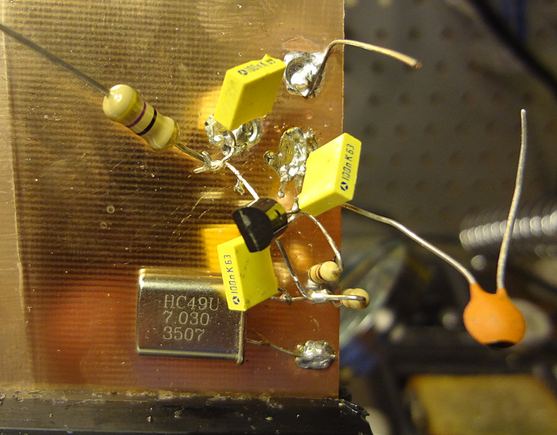
My first attempt at building a circuit using the ugly construction technique. It’s supposed to be a simple oscillator circuit using a J310 transistor.
One of the advantages of ugly construction is that if you’re working from a schematic or circuit drawing, building is pretty easy. I found that soldering components to the copper clad required a bit of patience, because it’s essentially a very large heat sink. Put the soldering iron on the copper clad, add solder until you get a good sized pool, leave the soldering iron in place and place the component.
For this particular circuit, Vcc is applied to the big resistor with the free lead and output is off the capacitor with the free lead. I soldered on a piece of wire to make the ground connection easier. Haven’t applied power to test it out yet. Will see if it works later on.
After getting a bit of advice from some locals about soldering, I thought I’d get in a little more practice with the SA602s and the breakout boards. It was also a good excuse to see how my new glasses are for working at the bench.
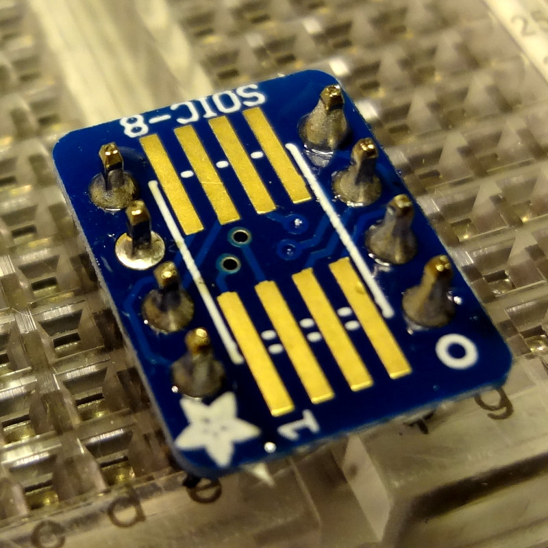
To get a little more room to work, I switched to a conical tip on the soldering iron and soldered the board onto the header pins first. This makes for a pretty stable platform to work on.
Adding header pins
Adding header pins
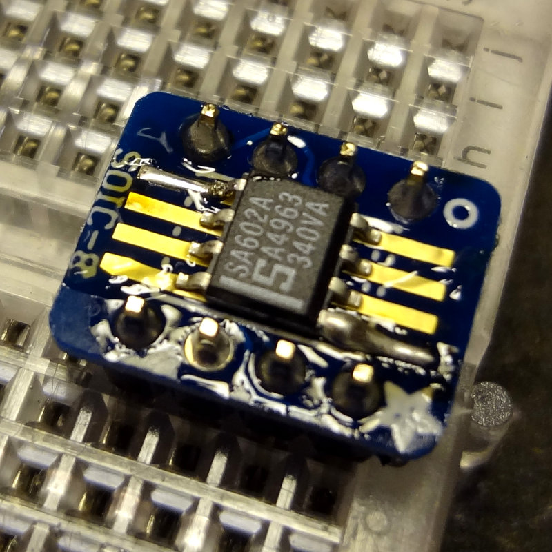
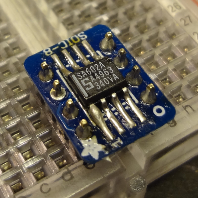
Add a little bit of flux paste, tin one of the pads and then tack on the SA602 to the tinned pad.
SA602 tacked on
Then flip it around and solder a pin on the other side.
Two pins soldered
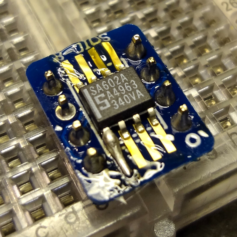
Then solder the rest of the pins, making sure not to leave the soldering iron on the board too long, and waiting a few seconds between soldering each leg to let things cool down a bit. A method that I found worked pretty well was to place the soldering iron tip on the pad, apply a touch of solder to the tip, push it towards the pin, and then draw the tip back along the pad.
SA602 soldered on
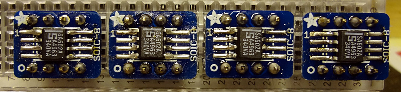
I soldered a total of 4 SA602s onto the breakout boards. Here’s the result of about an hour’s worth of practicing.
4 SA602s on breakout boards ready for experimenting
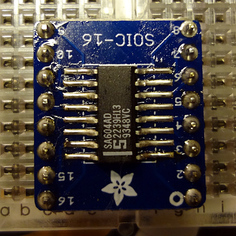
Using the same method, I soldered one of the SA604 chips onto the SOIC-16 breakout board. Although the SA604 is about the same width as the SA602, just longer, the SOIC-16 board is quite a bit larger than the SOIC-8 board. Having the header pins on the same side as the pads gives you a little less room to work with as well. Still, soldering the SA604 was pretty easy.
SA604 soldered onto a breakout board
My attempts at cleaning off some of the residual flux left some cotton fibers behind from the swab I was using. I don’t think it will affect how these work, but I’ll spend some time trying to clean them off.
I think I’m getting the hang of this now. Next, learn how to use these.
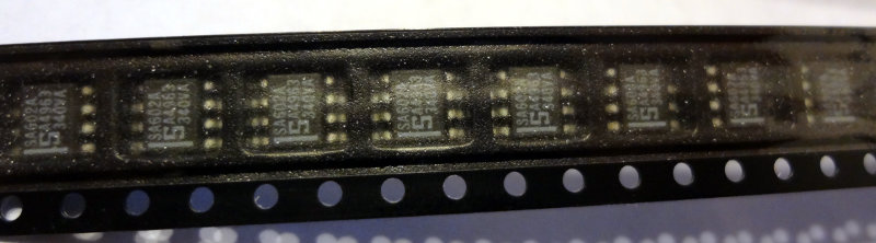
Last week, Dave/AA7EE announced that he had a bunch of SA602s and SA604s to give away. I emailed Dave to ask for some, and he sent me 18 602s and 6 604s. Thanks Dave!
These are surface mount ICs, so I ordered up some SOIC-8 and SOIC-16 breakout boards from Adafruit.
The package from Dave arrived earlier this week, and the breakout boards arrived in the mail today.
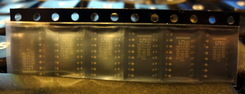
SA602 SMDs
SA604 SMDs
The breakout boards came bubble-shrink wrapped which was a little unexpected. I thought they’d just come loose in a ziplock bag or something.
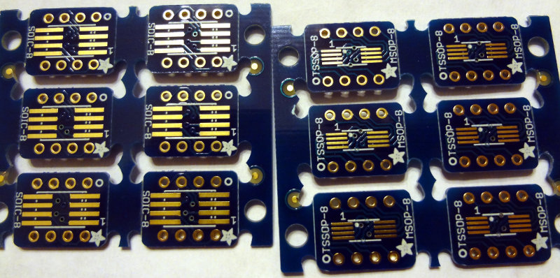
Adafruit SMD breakout boards
The boards are double sided, with SOIC-8/16 spacing on one side and TSSOP-8/16 spacing on the other side.
Adafruit SOIC/TSSOP 8 breakout boards
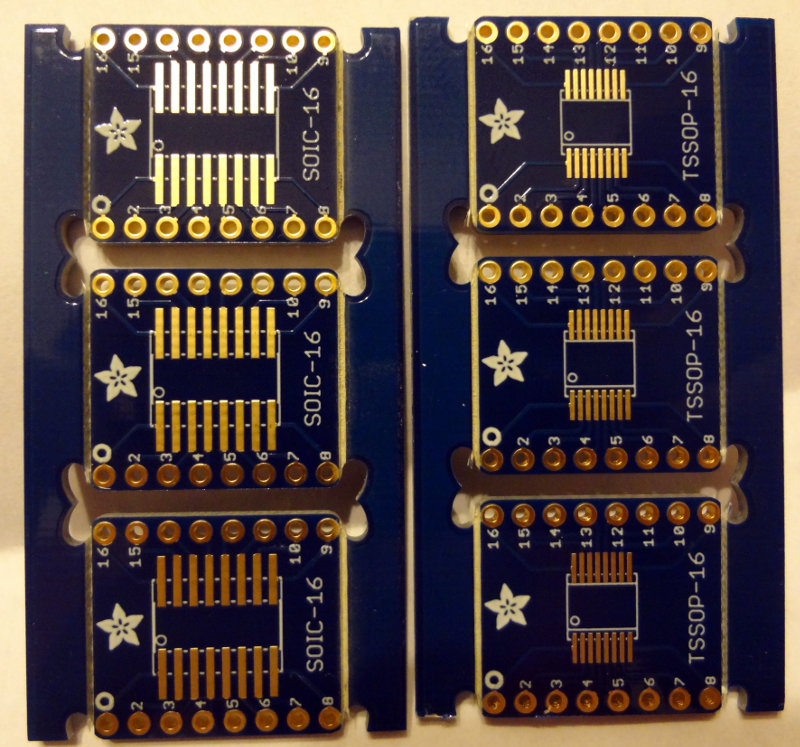
Adafruit SOIC/TSSOP 16 breakout boards
Interestingly enough, the SOIC-8 boards are half the thickness of the SOIC-16 boards, which are a regular thickness circuit board. Both have sets of holes (standard 0.1″ spacing) to solder header pins to, making them convenient to use in breadboard projects. Or you could just solder wires to them if that’s what the project calls for.
Off to the workbench to do some soldering. For SMD parts, these are actually pretty large, and soldering is relatively easy. First, tin one of the pads and then with tweezers, line up the IC and then heat up the tinned pad. Use the soldering iron to push the solder towards the IC pin and you’re done.
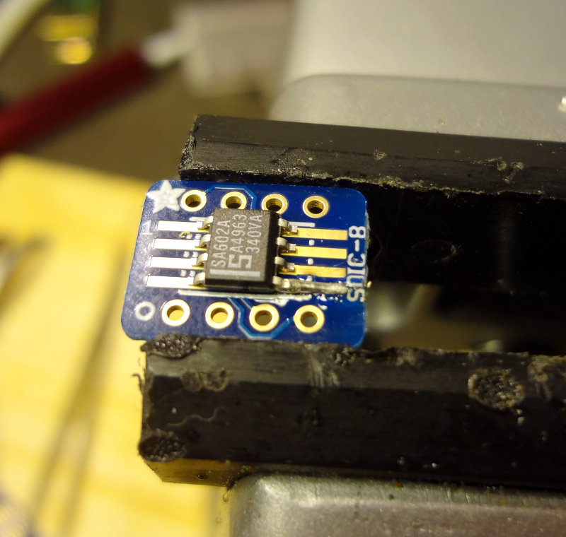
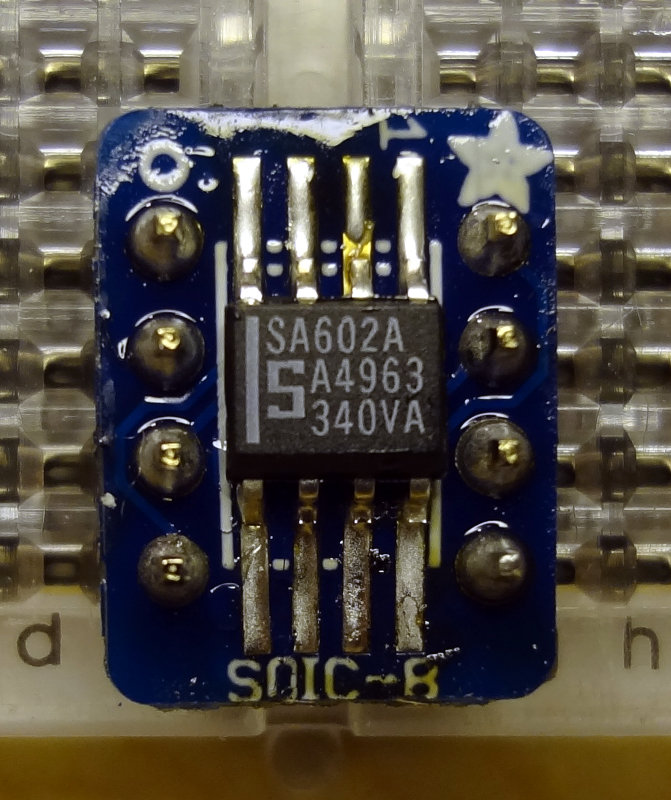
Soldering an SA602 to the breakout board
I used a toothpick to apply a little bit of flux paste to the rest of the pads, and then soldered the rest of the pins. That part goes pretty easily with flux.
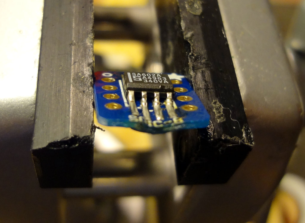
Pro tip #1: Don’t do this with the board clamped in a vise, or if you do, don’t leave the soldering iron on the board for too long. These SOIC-8 breakout boards are pretty thin and too much heat will make them melty. Oops.
Melted breakout board. Ooops
Once you’re done, it’s time to add some header pins. This part is easy. Stick the header pins into a breadboard, put the breakout board on the header pins and solder.
Adding header pins
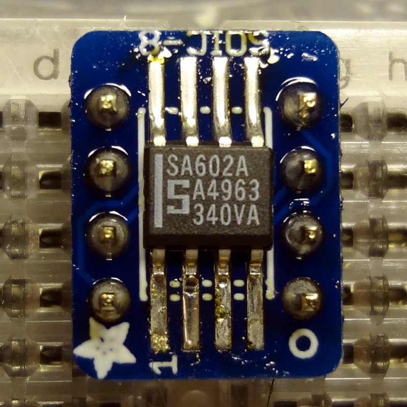
Pro tip #2: In your enthusiasm to solder, don’t forget to pay attention to where Pin 1 of the IC is supposed to go (ignore that bad solder job on Pin 2…easy to fix). That stripe on the SA602 should be where the 1 is printed on the board. Oops.