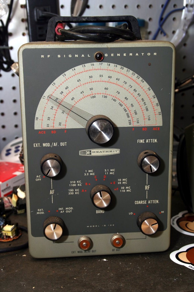
This time, I’ll replace that big orange capacitor with something newer (along with any other components that look like they need replacing). The signal generator doesn’t seem to be putting anything out at the BNC connectors anymore, so that will be another thing I’ll check.
Spent another evening poking around inside the Heathkit IG-102 signal generator, this time with schematic in hand and probing around with my DMM to check voltages in various places. I wanted to make sure everything was working ok, and it seems to be. The voltages I was getting were all pretty close (within 10%) of what was printed on the schematic.
I also replaced the original 60s or 70s era power cord with a polarized power cord (harvested from I don’t remember what now). It was a simple replacement and probably not critical but I figured having a new(-ish) cord might make it a little more electrically safe. The hard part was unsoldering the old cord and getting the plastic strain relief thing out of the chassis.
I was able to set my HT to a few frequencies in the 10-30 MHz range and heard tones when I adjusted the signal generator to those frequencies. That seems like a good sign it’s working.
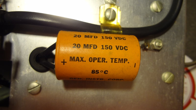
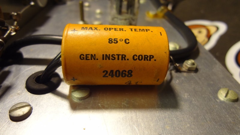
The Heathkit IG-102 signal generator has this big 20 μF 150VDC electrolyic capacitor that has 2 leads on the positive side and one lead on the negative side. It looks like an axial capacitor, but I’ve never seen one with two leads on one side before.
20 μF capacitor
20 μF capacitor
Although it doesn’t seem to be showing any signs of failing, given the unknown age of the signal generator I thought it might be a good idea to replace it with something new. I’m thinking I should replace it with two caps, one for each lead on the positive side. Don’t have any axial caps in the parts bin, but there are plenty of 20 and 22 μF radial electrolytic caps. No new 20 μF caps though.
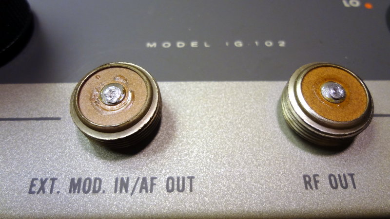
Did some surgery to replace the old connectors on the Heathkit signal generator with BNC connectors.
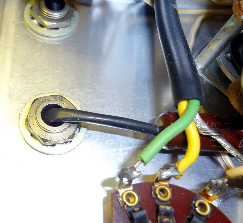
Heathkit IG-102 old style connectors
I thought it might be a bit of a challenge, but turned out easier than expected. The center of the connectors turns out to be just a hole/eyelet, so a bit of heat on those center contacts to melt the solder was enough to free the wires connected to them.
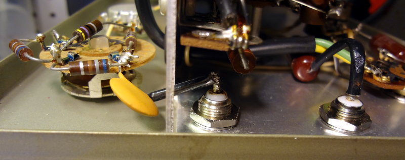
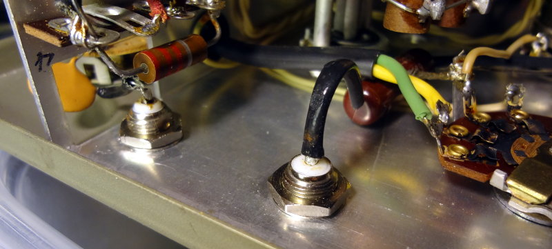
Behind the connectors
Behind the connectors
Once that was done, it was a simple matter to remove the connectors and replace them with a couple of BNC connectors. Solder the wires into the center connector of the BNC and done! While I was at it, I also replaced the yellow 0.01 μF capacitor with a new one.
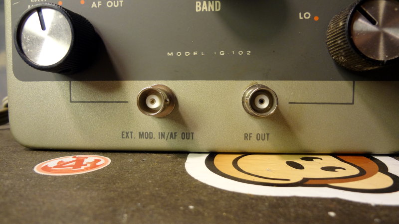
New BNC connectors
New BNC connectors
Looks pretty spiffy and modern now with the BNC connectors. Still not entirely sure if it works or how well it works, but at least now it’ll be easier to connect the signal generator to stuff.
After going through the manual for the HD-10, I learned that the terminals on the rear of the HD-10 could be used to attach a key. So off to the garage I went to put some terminal connectors on some wires to use to hook up the J-38 key to the HD-10.
It took a couple of tries before I figured out where the wires were supposed to go on the J-38. There are lots of pictures of J-38 keys on the internet, but not too many that show how the wires are supposed to be attached (the terminals are the two on the inside).
J-38 straight key and HD-10 keyer
With everything connected, tapping the key made the keyer make noises and I managed to make some Morse Code sounding noises with the key. Now they can sit on the desk next to me so that I can practice tapping out Morse Code whenever I feel like.
I still need to take the key off the base and clean it up a bit, and then make up a cable that I can use to plug the J-38 into the radio with. Also thinking about seeing if I can find a nice block of wood to attach the J-38 key to for a more solid base and to elevate the key a bit.