CC1’s whine

Using Audacity, I was able to finally get a decent recording of the whining noise that my CC1 is making (the recording isn’t very loud so you might have to turn the volume up).

The audio clip starts with CC1’s startup message (“CC1”) followed by the whining noise, and then the Morse code readout of the frequency and then more whining. Of interest I think is that the whining is muted when CC1 is playing the dits and dahs. Not sure if that says anything about where the source might be.

Using Audacity’s frequency analysis tells me the main frequency of the whine is around 1300 Hz with second and third harmonics at around 2600 and 3900.

CC1 whine spectrum
CC1 whine spectrum

Still haven’t had much luck figuring out what’s making it, although Jason/NT7S has given me a few helpful tips. I need to check and make sure the BFO is oscillating and check to make sure there are no open circuits in the toroids. Haven’t found anything yet. Need to put CC1 back on the bench and have a closer look at everything.

While I was checking the signal paths through the toroids, I decided to go ahead and make some modifications to the IF filter suggested by Jason to improve the signal leakage. Didn’t expect them to have any effect on the whining, but I figured I’d make them anyway.

I’m enjoying this detective work trying to figure out what I did wrong with CC1. It’s almost as fun as putting it together.
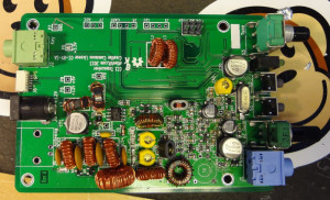
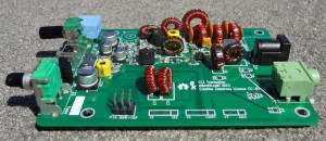
CC1 deaf and whiny

CC1 seems to work, but all is not well I think. Attached a 50 Ω BNC terminator and applied power, but I was hearing this whining noise that I didn’t remember hearing before. Apparently it’s normal and is a result of clock in the DDS part of the radio. It’s supposed to be fixed by a firmware update, but applying it didn’t help with my radio. Since there are 4 other CC1s completed that don’t seem to be doing this, it’s probably something wrong with mine. Not sure what the problem is yet. I think I might have to find someone with a working oscilloscope to do some probing around with. Whiny.

Finally found a BNC/SO-239 adapter at Hurricane Electronics/Radio Shack up in Summerville. Used it to connect CC1 to the antenna and was hoping to hear something, but if there was anything, I couldn’t hear it over the whining noise. Tried tuning around to some frequencies where I could hear CW activity on the big radio, but wasn’t able to hear anything when I tuned to the same frequency on CC1. Deaf, or at least hard of hearing.

Was hoping I’d be able to get CC1 operational, but it looks like it needs some troubleshooting. In the meantime, there are a couple of hardware modifications that need to be made to T1 and L5, which I’ll try to get to soon.

CC1 completed

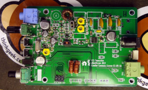
Got the last of the toroids wound and put onto the board. Now CC1 is complete!

CC1 completed
CC1 completed
CC1_04

The BNC connector was put on after I snapped these photos.

Everything sounds like it works when I apply power. I need to get a BNC/SO-239 adapter so that I can connect it to the antenna to test the receiving and then try to make myself a dummy load to test the transmit. After testing everything out, (haven’t worked out yet how I’ll test the power output, but I’ll think of something), it will be time to work on drilling holes for the end plates of the enclosure.

CC1 almost complete

The CC1 kit is getting closer to being completed. All the tiny bits are soldered on, and now there’s just the toroids left to wind. I put T1 and L4/L5 on last night and now there are just 8 inductors left to wind. No lost pieces, only one extra part (which was extra to begin with) and only two fried components.

I discovered when I went to install R50 that I had accidentally installed it in the R26 position. They’re both the same resistance, but R50 is a larger resistor. In my haste, I must have just grabbed the first 100 ohm resistor that I saw and put it on. Fortunately I was able to get it off the board without too much fuss and put it where it belonged.

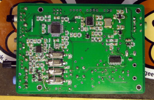
Back of CC1
Back of CC1
CC1 just needs toroids

I also found that installing U2 and Q9 is a whole lot easier with lots and lots of flux on the board. Wish I had known that when I installed U1 and U5.

I better get cracking on learning Morse code!

CC1 lives!

CC1 works!

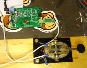
Soldered the L12 and L13 inductors (heat strippable enameled wire rocks BTW), made up a cable to connect the straight key (CC1 is really designed for a paddle, but I made the straight key work) and plugged in some headphones.

Testing CC1
Testing CC1

Applied power and CC1 greeted me by beeping ‘CC1’ in Morse code. Tapped the key and got a stream of dits. Grounded the other wire and got a stream of dahs. Pressed the S1 button and got an ‘S’ and pressing S2 gave me the frequency (I could only copy an R and 8 in the string of numbers).

Started work on the next section, the Mixer/IF/Product detector/BFO. With the connectors and larger caps, some of the pads on that section of the board are starting to get a little hard to access with the chisel tip on my soldering iron. If I’m going to do more stuff like this, I’m going to have to find myself a narrower chisel tip to work with.

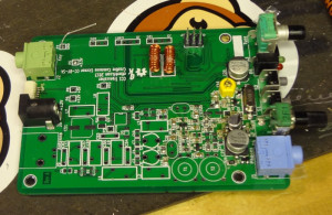
CC1 Mixer/IF section

About one quarter through this section of the build now and starting to get into the band specific components. I’ll be building my CC1 for the 40m band. Quite pleased with how things are going so far and I’m learning quite a bit.