The templates for the faceplates I made worked out pretty well. The holes weren’t perfect, but I blame that on using a drill to make the holes. Would have been much easier if I had a drill press, or ideally a hole punch. For the BNC hole, I didn’t have a 1/4″ drill bit so I just used a 3/8″ bit (the largest I had) and my Dremel with a sanding drum to enlarge the hole.
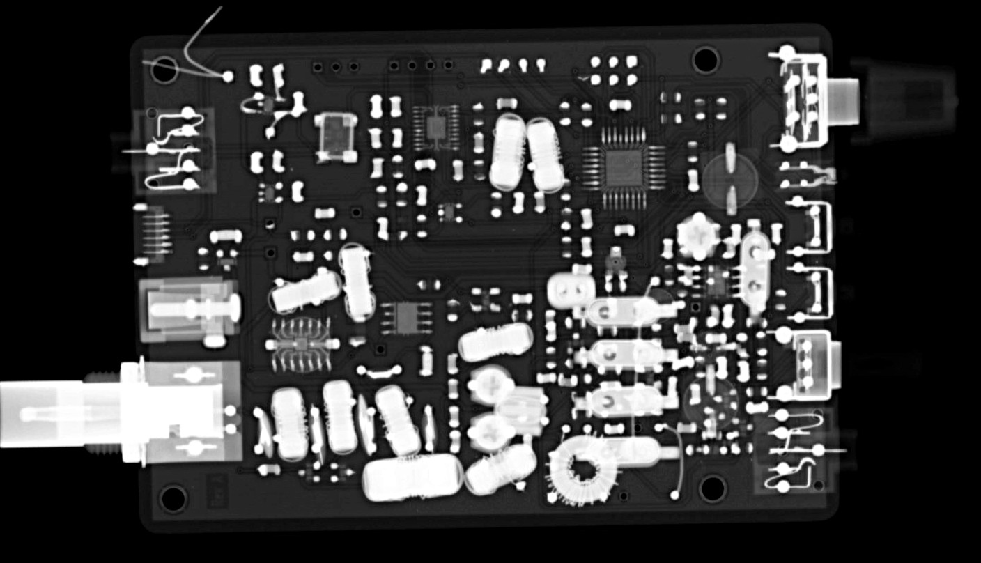
CC1 enclosure
CC1 enclosure
Looks pretty good in its enclosure I think. Now I need to put some labels on it.
Update: After a couple of iterations with paper, some of the measurements were adjusted and the drawing updated. I’m pretty sure the measurements are accurate and will serve to help other CC1 builders create a drilling template for their build. As always, keep in mind the “measure twice, cut once” principle. YMMV. Links to my templates are at the end of the post. Feel free to use them as a starting point for your CC1 build.
In preparation for drilling out the holes in the face plates for the CC1 enclosure, I used my digital calipers to measure the distances to the center of each of the connectors that would need a hole.
First I started measuring while holding it in my hand, but I realized there’s a little bit of play when the board is in the enclosure and measurements would change depending on how I was holding it.
I decided to place CC1 and enclosure on the table and starting with the left-most connector (A), measure it’s position relative to the left and bottom edges of the enclosure. For the remaining connections, I just measured the offset from the first one since their positions are fixed. Seemed like the most accurate way of doing things.
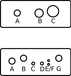
The face plates are 74mm x 29mm. The top one is the back plate with the largest hole corresponding to the BNC jack. The bottom one is for the front plate. The Dia version should be to scale, but when I printed it, it was just a tiny bit short along the x-axis. Apparently printer scaling and computer scaling is a tiny bit different. It should still be pretty close to use as a template though. Will try cutting it the paper version to see how well it fits before I start drilling.
These are the measurements I came up with
Front plate.
Measurement for A is relative to the left and bottom edge. Measurements for B-G are relative to A.
Hole
X (mm)
Y (mm)
(X, Y)
A
12.5
15.5
(12.5, 15.5)
B
+12
+3
(24.5, 18.5)
C
+22
-2.5
(34.5, 13)
D
+31
-2.5
(43.5, 13)
E
+38
-3.5
(50.5, 12)
F
+38
+0.5
(50.5, 16)
G
+48.5
+3
(60.5, 18.5)
Back plate.
Measurement for A is relative to the left and bottom edge. Measurements for B and C are relative to A.
Hole
X (mm)
Y (mm)
(X, Y)
A
18
15.5
(18, 15.5)
B
+22.5
0
(40.5, 15.5)
C
+37
+2
(55, 17.5)
Template files. Download these to use as a starting point for your build.
My CC1 is on its way back from Jason/NT7S. Turns out the whine in CC1 was due to the wall wart I was using. He also found a pin on one of the chips that I missed soldering and fixed that. Once he did that, CC1 was working just fine.
Nice to know that I’m starting to develop some proficiency with soldering things. Yay for adding skill levels!
After digging a bit into the manual and figuring out what buttons I should be pressing, I was finally able to get the oscilloscope to give me some waveforms at some of the test points on CC1. No indication of what the time base is (have to figure out what buttons to press to make the text display again) but it’s progress at least. I’m just tickled that I’m able to get any kind of waveforms at all.
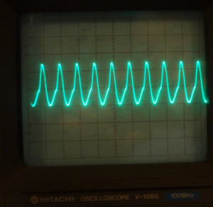
This is the nice sine wave out of the U6 50 MHz oscillator chip
CC1 oscillator waveform
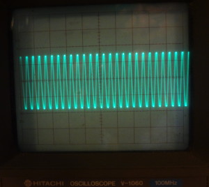
At the BFO test point, this is what I got
CC1 BFO waveform
Based on this, the BFO would seem to be in good shape.
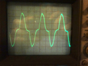
At the VFO test point, the trace looks like this
CC1 VFO waveform
It was tough to get a stable trace out of this, and I had to wiggle the probe around a bit before I could get the waveform. I wonder if that could be an indication of any kind of problem.
Diagnostic work continues on CC1 and now I have another tool I can use on my workbench. There’s still a bunch of stuff I need to learn about this scope, so I’ll be spending more time with the manual. There’s supposed to be some text on the display as well which I think I made go away in my earlier attempts at playing with the scope. Need to figure out how to bring those back.


