After my recent acquisition of the Hallicrafters HT-32, a thought popped into my head: What does the boat anchor/vintage radio of the future look like.
Go to any hamfest or talk to any long time amateur radio operator, and it won’t be hard to find 40+ year old radios still in working condition (some better than others). Even if they’re not working, it’s not impossible in most cases to find parts to resurrect the radio.
I’ve got 3 Hammarlunds and 1 Hallicrafters in my boat anchor collection now. Our Kenwood TS-480SAT or Elecraft K2 could be considered vintage, depending on what time frame for vintage you want to use. Should they be considered part of the boat anchor collection?
In the age of (current) modern, IC based, software-defined radios (pretty much anything from 2010 onward), how many of those will remain servicable/fixable enough to become the boat anchors of the future? Will anybody be using an ICOM IC-7300/7300MK2 or Yaesu FTDX-10 in 2050? Will I be able to repair our Kenwood TS-480SAT in 2040 when something fails?
Ask anyone of a certain ham radio age what a boat anchor radio would be, and you’ll get answers like Drake, Collins, Hallicrafters, Hammarlund, National. What will people say in 2040 or 2050? What boat anchor radios be we be using 20-30 years from now?
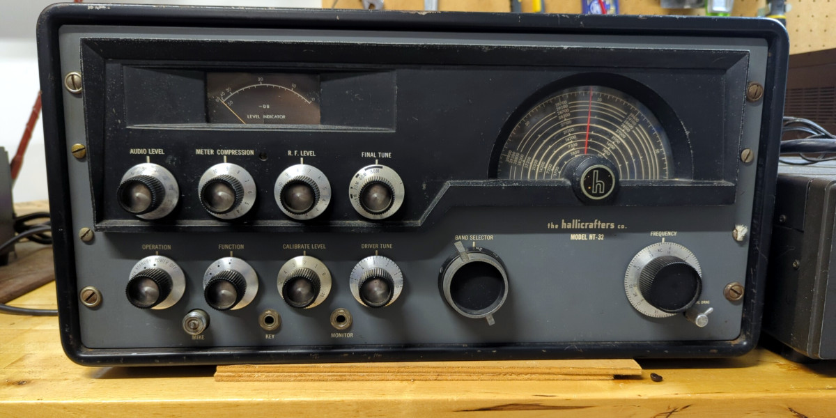
Joining the vintage radio collection this week is a Hallicrafters HT-32 Mark I transmitter I acquired from a local ham who wanted to see it go to someone who would put it back on the air.
The HT-32 works on 5 bands (80, 40, 20, 15, 11/10m selectable by crystal), does SSB, CW, and DSB (double side band, AM without the carrier). Maximum power output is 100 W in SSB/CW mode and 25 W in DSB mode.
An old Hallicrafters HT-32 amateur radio transmitter sitting on a workbench
At 50.7 cm (W) x 25.6 cm (H) x 43 cm (D) and weighing in at just under 40 kg, this radio is a BIG HEFTY beast. This is the kind of radio where you set it down somewhere in the house and built your shack around it. None of this “Oh, maybe I’ll move it over to this side of the room”. No. Once you’ve set it down that’s where it’s staying.
When I arrived to pick it up, the previous owner had it plugged in with a light bulb connected to the antenna connector for a dummy load. Everything seems to be in working order, and there was enough RF output coming through the antenna connector to light up the light bulb. The brightness of the light bulb modulated nicely when he spoke into the microphone, so that seemed like a good sign. Wasn’t able to verify what the transmitted RF sounded like, but once I get it on the air I’ll find out soon enough. The previous owner mentioned he had done a full alignment on the receiver, but that was quite a while ago. Hopefully nothing has drifted or changed in the meantime.
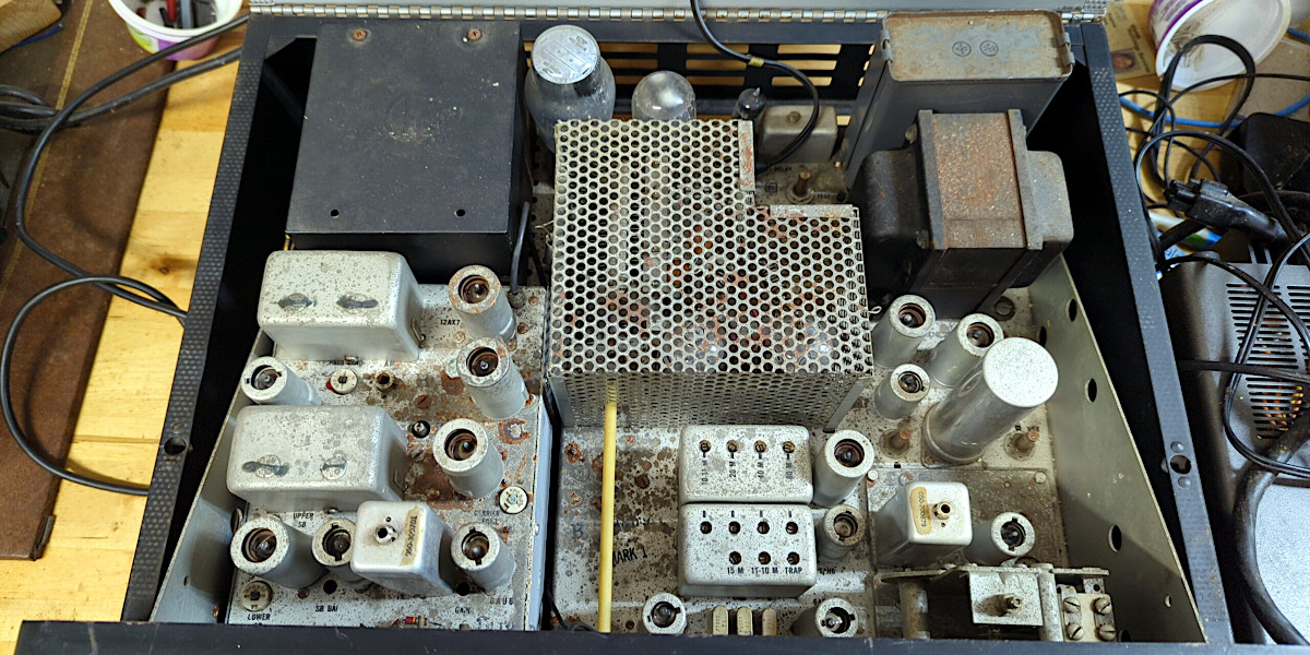
The radio is in pretty good condition for its age, with some light surface corrosion (what 70 year old radio wouldn’t). The top metal mesh cover flips open to reveal an assortment of tubes, capacitors, tuned inductors, and a big chunky transformer.
Under the Hallicrafters HT-32 lid
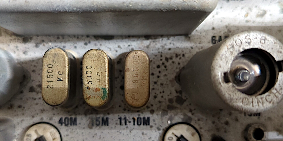
One of the three crystals in the radio can be used to set up the HT-32 to work in either the 11 m (CB now) or 10 m band.
Three crystals in the Hallicrafters HT-32. The crystals are marked 21500 kcycles, 25000 kcycles, and 30.9 MHz.
The crystals are used to mix the SSB signal from the second mixer stage to produce the output frequency for that crystal’s band. The 11-10 m crystal can be switched out for operation in the 11 m band, or different 500 kHz segments of the 10 m band. The radio currently has a 30.9 MHz crystal which sets the radio up for operating in the 11 m band (26.96 – 27.23 MHz).
I haven’t pulled the radio out of the chassis yet to see how things look underneath. I expect that the rest of the radio will look fairly similar to the top.
I’ll have to figure out how to wire up a microphone to the radio. It looks similar to the connectors on the Heathkit IG-102 that I replaced with BNC connectors. A bit of research tells me that it’s an Amphenol 75-MC1F/Switchcraft 2501 connector. Wonder if I can find a working microphone with one of these connectors on it already.
Fortunately it also came with the manual, which I promptly scanned and made into a PDF. The manual also conveniently has the schematic for the radio. I’ll have to spend some time studying the manual to learn how to use it before I try to get this paired up with one of the Hammarlunds and get it on the air.
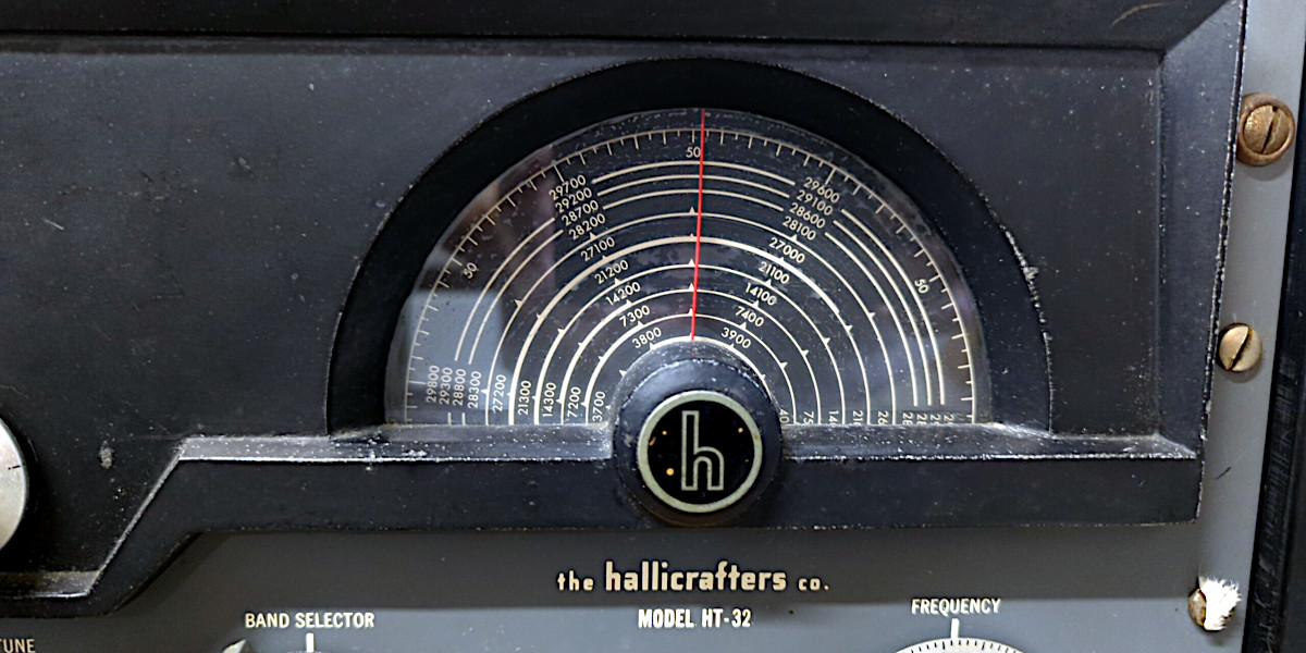
Hallicrafters HT-32 frequency dialBottom right of the Hallicrafters HT-32 frornt panel showing the band selector knob and frequency dial knob.Lower left row of knobs on the Hallicrafters HT-32
Looking forward to getting this radio set up and working.
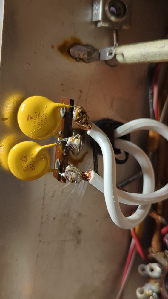
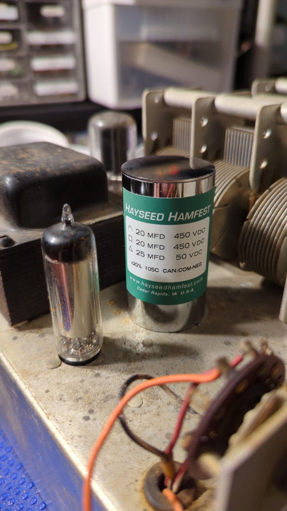
The HQ-100 has some new Class X2/Y1 capacitors across the AC input, a polarized two-prong power cord, a new multi-section can capacitor from Hayseed Hamfest, and now three “new” tubes.
New capacitors installed in the Hammarlund HQ-100
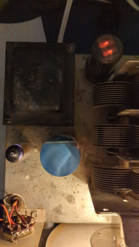
After spending a few days checking over things, I put the front panel and knobs back on, plugged the radio in and was greeted with some warm glowing lights.
Hammarlund HQ-100 plugged in and showing some nice glowing lights.
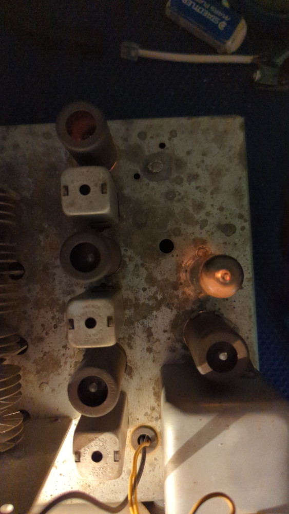
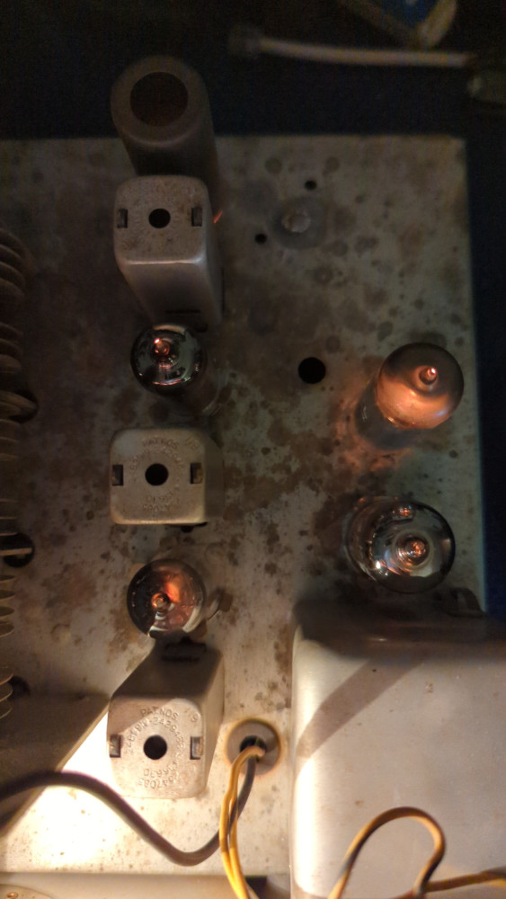
The two lamps behind the frequency dial indicator both came on, and a nice warm red glow was coming from most of the tubes. Three of them (a 12AX7 and two 6BA6s) were dark though. Fortunately I had acquired all the tubes I needed for the HQ-100 at past hamfests. After replacing the three tube and applying power again, all the tubes were lighting up!
Replacement tubes lighting up
Next step will be to attach a speaker and antenna and see how well, if at all, the radio receives.
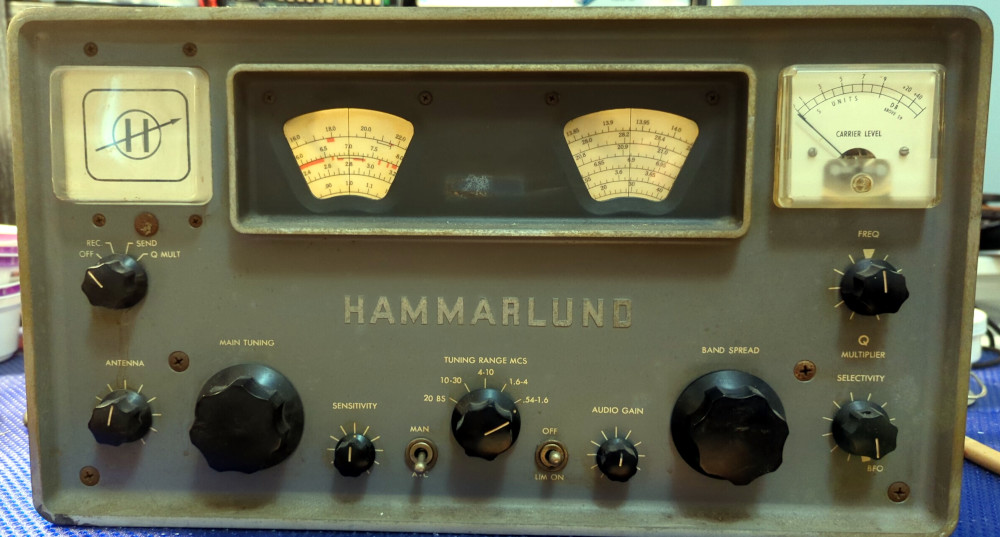
At long last, the Hammarlund HQ-100 I picked up a few years ago is finally getting some time and attention on the workbench.
Hammarlund HQ-100 receiver
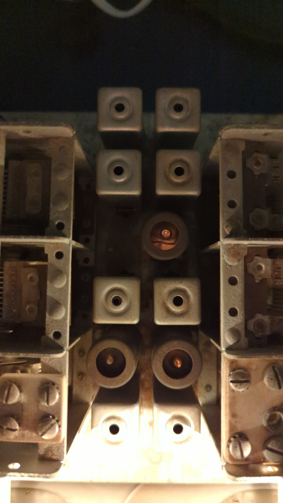
After a bit of cleaning outside, it was time to dig in and see what was going on. Removing the knobs and four slightly rusty screws let me remove the front panel to see if the band spread tuning dial could be fixed.
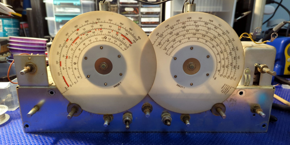
Exposed tuning frequency indicator dials after removing the Hammarlund HQ-100 face plate
Turns out the frequency indicator dials (the large white disks) are connected to the tuning dial knob by friction fit. Turning the knob makes the indicator dials turn, and the shaft those dials are attached to are connected to the variable capacitors that do the tuning. The band spread dial was free-spinning because there wasn’t enough friction between the indicator dial and the tuning knob. While I was trying to figure out how to fix it, I discovered the nut at the back end of the tuning shaft was loose, and tightening that up made the tuning knob work again.
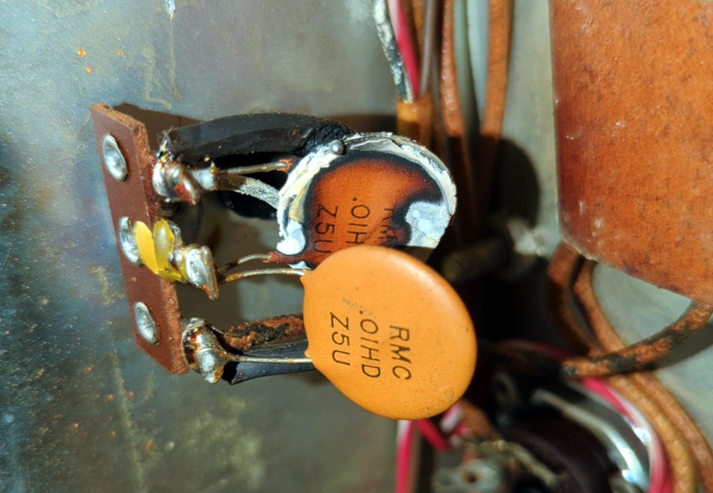
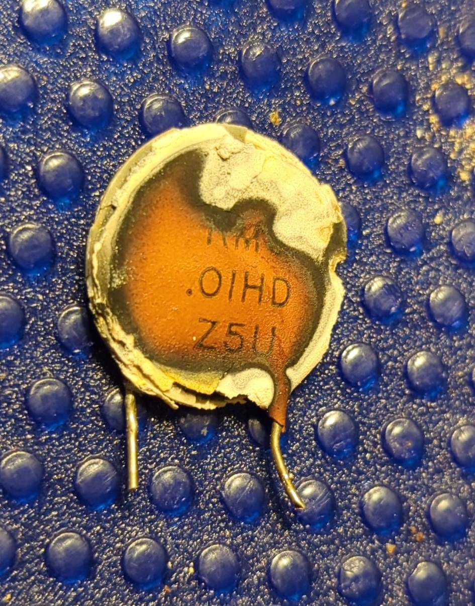
The other big issue I came across while looking around was a burnt capacitor across the AC input.
Burnt capacitor on the AC inputBurnt 0.01 uF capacitorAC filtering caps
Not a good thing to see. I clipped the toasted capacitor out as well as the old two-prong non-polarized plug. I’ll see about wiring in a new three-prong plug and maybe a fuse as well.
Haven’t seen any other obvious component issues yet. There’s a multi-section electrolytic can capacitor that probably should be replaced, but there aren’t any signs of leakage.