To celebrate the 10th anniversary of meeting Connie and me getting my amateur radio license, we went back to the Atlanta Hamfest this past weekend.
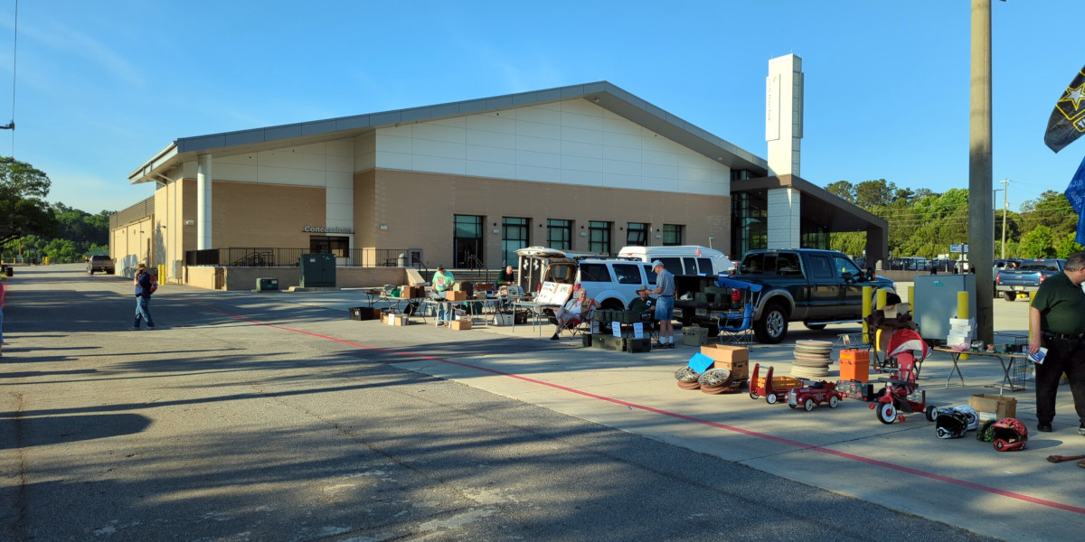
This was our first trip back to the Atlanta Hamfest since the last time we went back in 2014. The 2022 edition of the hamfest was back at the Jim Miller Park with a shiny new events building.
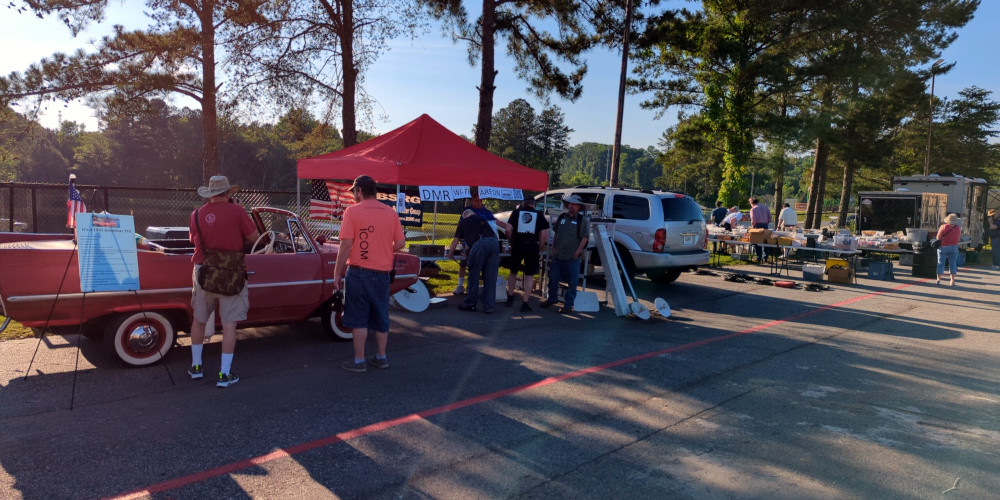
This year, the hamfest was quite a bit smaller in terms of the bone yard and vendors inside but considering the times, I thought the turn out was still pretty decent. Apparently there were a number of last minute cancellations so there wasn’t much in the way of commercial vendors at the hamfest this time. We still found a few things to buy from the swaps and people out in the bone yard though.


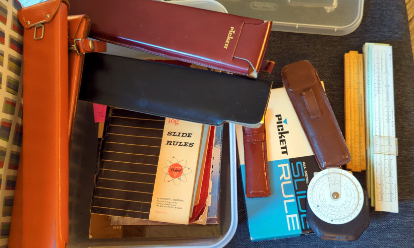
The hamfest acquisition I’m most excited about is one that Connie came across: a bin of slide rules and slide rule books including a neat little round slide rule. This will expand my slide rule collection quite a bit. Some of the larger slide rules have scales I haven’t come across before, so I’m looking forward to learning about those and how to use them.
Other acquisitions included a couple boxes of ferrites and toroids, an Astron RS-35 power supply for the shack, and a stack of QRP Quarterly magazines someone was giving away.
Part of our day was spent serving as volunteer examiners for the testing session being held at the hamfest. We helped out with the afternoon shift, and had about 5 people taking tests in the afternoon. Most of the test takers were in the morning shift and it sounded like it was pretty busy.
Even though the hamfest wasn’t as big as the previous years we went, we still had a really good time.