A new radio kit is on the way and should be here by the weekend. Ordered a beta version of the CC1 QRP transceiver kit from Jason/NT7S. Looking forward to getting it and blogging the build here. It’s small with a lot of SMT components, so I’ll definitely be stretching my soldering skills with it. Learned a lot by doing the Softrock Lite receiver, so I think I should be able to manage pretty well with this one.
Category: Homebrew
Softrock Lite II enclosure
No empty Altoids tins around, but I did have an empty tin that used to hold some tea bags. It was the perfect size to hold the Softrock Lite II and a 9V battery.

Punched a couple of holes into the tin so I could secure the board and instant enclosure!
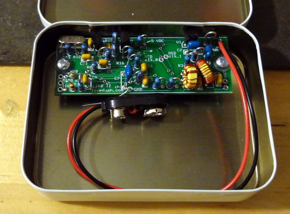
On the right side I think I’ll see if I can make a hole to attach a BNC connector for the antenna. On the left side I’ll make a small hole to run the cable out to the sound card.
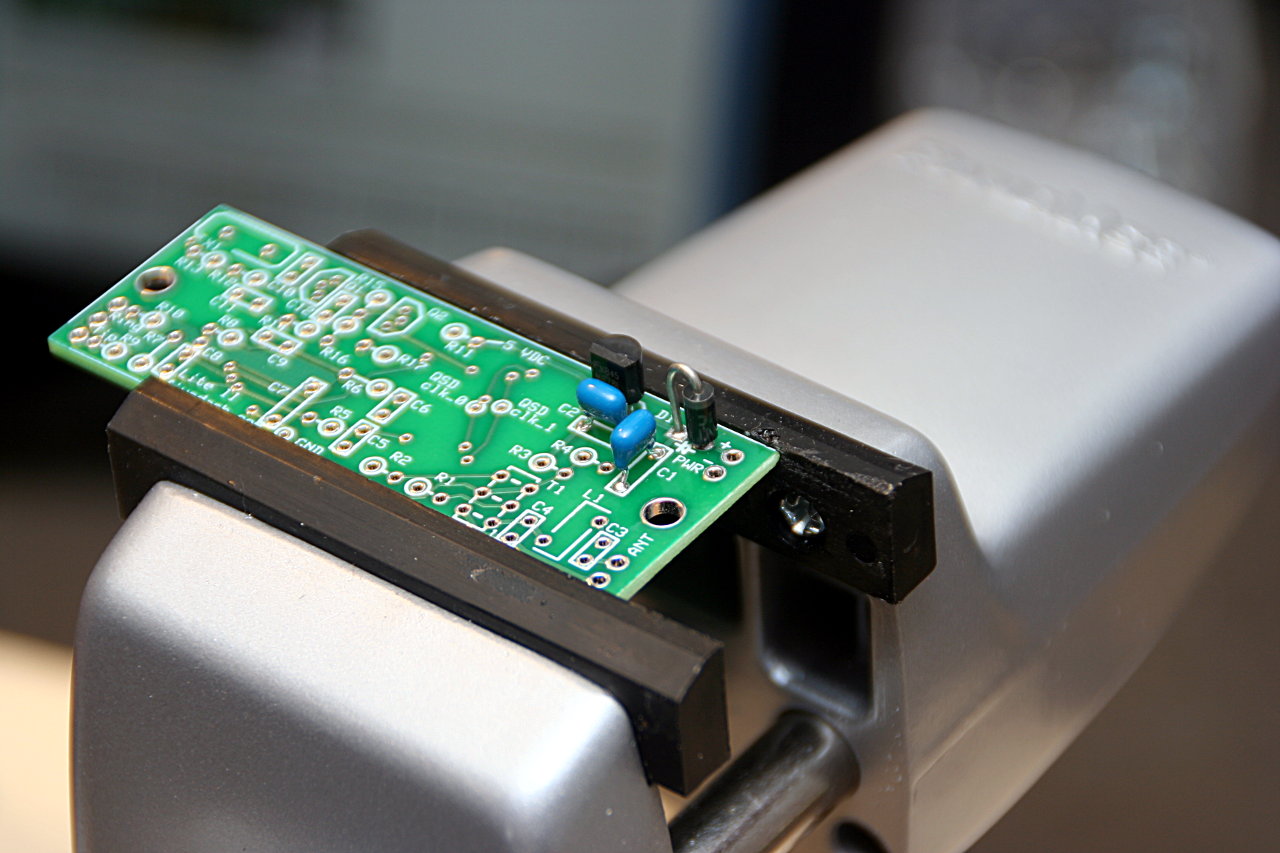
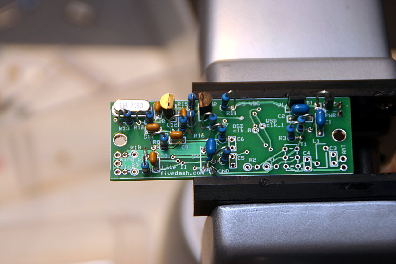
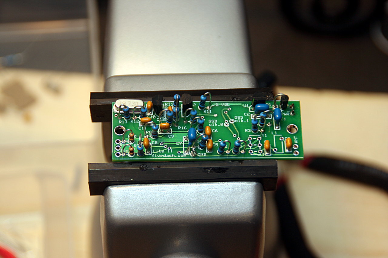
Softrock Lite II completed
Finally got around to putting the last components on the Softrock Lite II receiver. It passes all the voltage tests, which seems like a good sign. I replaced the breadboard jumper terminals with a 9V battery connector to make it more portable. Now all I need to do is make an antenna connector and a wire to a sound card and I should be up and running with it. I’ve got a short length of coax with an SMA connector on it that I can use for the antenna connection, and I’m pretty sure I can find something in my junk box to cannibalize for the sound card connection.

Building the Softrock Lite II
Finally got around to starting one of the Softrock radios I got a few months ago. Decided to start with the Softrock Lite II receiver since it was the easiest and didn’t have too many SMT components to put on. Most of the components are through-hole, with a few SMT capacitors, ICs and an op amp. Perfect for starting off with SMT work.
It’s a pretty easy build, and the build instructions are pretty thorough and informative. The instructions break up the build into the different sections of the radio, explain what it does and provides the schematics, list of parts, where to put them on the board and tests afterwards.
I did run into a couple of problems with getting the SMT capacitors on. One of them was the wrong one (didn’t take note that one set was marked and the other wasn’t), and two of them I put in the wrong orientation because I wasn’t paying attention to the diagram. Other than that the SMT work turned out to be a little easier than I thought it would be.
The build starts with the power supply part of the radio. All through hole stuff, except for one SMT capactior, so pretty easy. Just need to pay attention to the orientation of the diode.
I used a couple of jumper pins and used power from the MiniLab to supply power to the radio for testing. The oscillator part was next. Again, all through hole stuff and one SMT capactior here for this section of the radio.

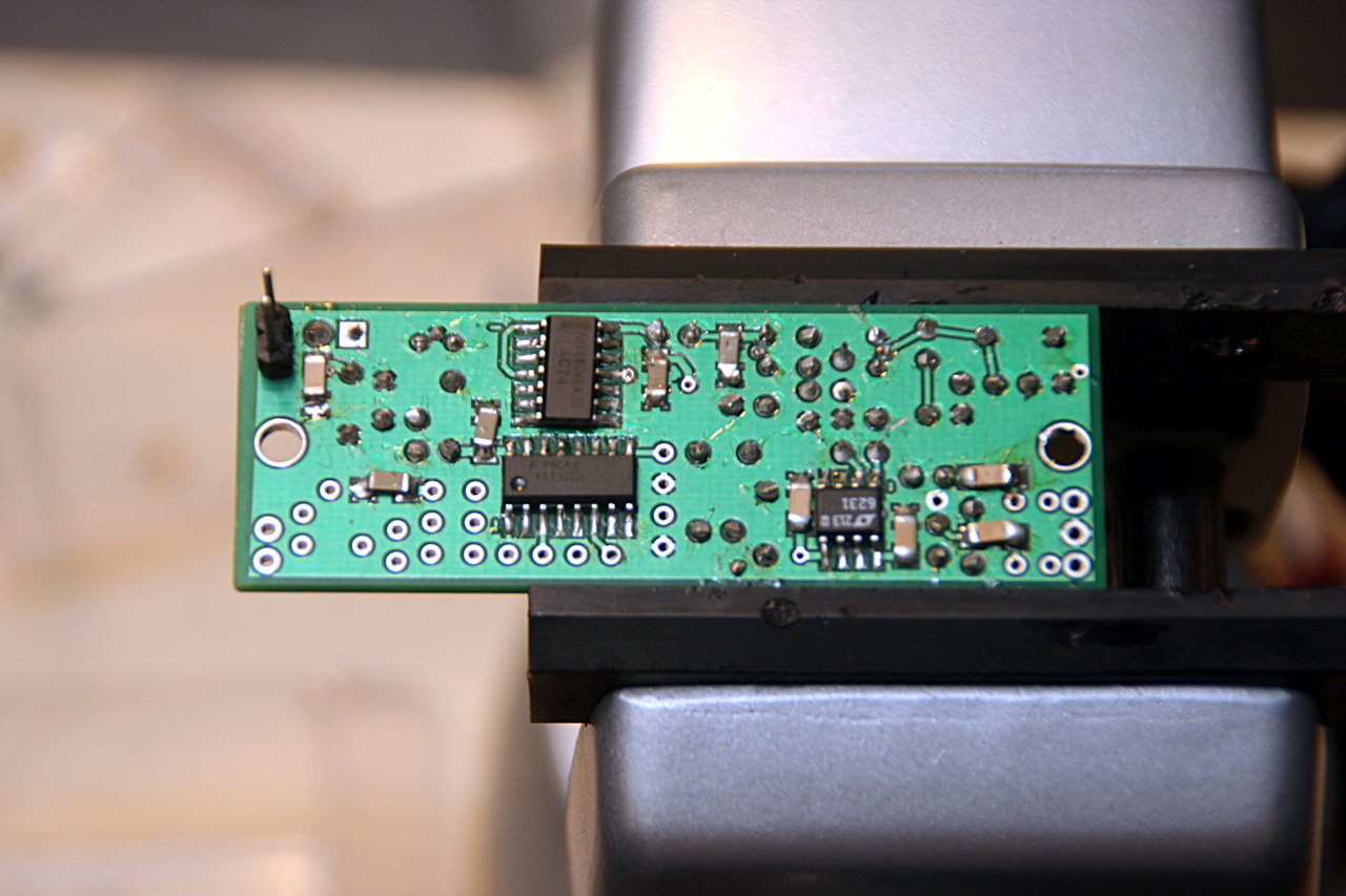
Most of the SMT components are in the divider and op-amp stages of the build. There are 3 SMT ICs and the rest of the SMT capacitors that go on in this part. With a bit of practice from the first two SMT capacitors, getting the rest of the capacitors on wasn’t too hard (aside from not paying attention to orientation). The SMT ICs and op amp were a little trickier, but still not as bad as I expected.
Except for the inductor and transformer in the band pass filter stage, all the components are on the radio. Will need to study the section on winding toroids first before I try to make them. Then I’ll have to switch out the jumper pins for a more permanent power connection and then make up the computer and antenna connections.
An OpenBeacon to play with
Thanks to Matthew/W2MDW, I now have an Etherkit OpenBeacon to play with.
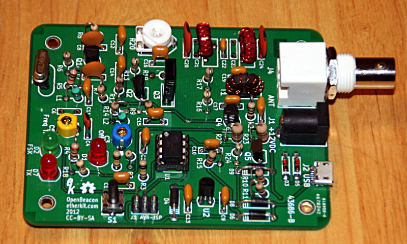
It’s a kit that I’ve been thinking of getting to play with in the near future. The one Matthew sent me was one of the early beta models and has had some modifications done to it, but it works. He didn’t have much time to mess with it anymore and thought I could put it to good use.
I’ll need to get an antenna for it and figure out how to program it, but it shouldn’t be hard to get on the air.
It looks like a pretty easy kit to build, so I’ll probably pick up one of my own to assemble and get up and running. Looking forward to getting this one going and seeing who picks up the signal.
I wonder how hard it would be to modify to broadcast on 6m.