New 2m shack radio

With the old 2m radio installed in the car, it was time to install the new 2m radio in the shack to replace the old one. We picked up a Yaesu FT-2980 a couple months ago and this weekend’s project was to get it up and running.

A 2m ground plane antenna was installed in the attic a few weeks ago, but I ended up having to reposition it to make it easier to run the coax into the shack. Once that was done, I was able to feed 50 feet of RG-213 coax through the conduit running into the shack with about 10 feet left over which got coiled up next to the antenna.

After a bit of running up and down between the attic and shack, I got the antenna trimmed enough to get ~1.1 SWR across the band.

The weekly ARES net gave me a chance to test out how everything sounded and see how well I was able to get into the nearest repeater. At first, it didn’t seem like I was being heard on the repeater, although I could hear everything going on. After looking up the repeater details, I discovered that I had the wrong CTCSS tone set. Once that was fixed, I had no problem being heard on the repeater.

On a good note, the radiant barrier on the roof sheathing seems to have absolutely no effect on the radio’s ability to pick up RF (in the 2m band at least). I wasn’t expecting the radiant barrier to have any effect, but I occasionally see people in forums say they’re bad for radio. I suppose that would depend on the type of radiant barrier that’s installed. The barrier on my house is just a thin layer of shiny foil type material glued to the back of the roof sheathing and as far as I can tell, doesn’t have any effect on the radio’s ability to hear the local repeaters.

Mobile radio in the car

I finally have a radio installed in my car!

The radio is a Yaesu FT-1802 2m rig that I picked up at the Charleston Hamfest a few years ago. After using it in the shack for a while, it’s finally going mobile thanks to a lot of help and advice from my father-in-law.

I thought running the wires from the radio to the battery would be the tough part, but the hardest part turned out to be finding a decent place to mount the radio. Using a fuse tap to run power from the in-cabin fuse box to the radio turned out to be pretty easy. No need to fish wire out into the engine compartment and to the battery.

Fuse tap connected to the in-cabin fuse box to run power to the radio
Fuse tap to run power to the radio

The best place we found to mount the radio turned out to be against the side of the center console on the driver’s side. It provides reasonable access to the radio and is pretty out of the way. The side panel popped off pretty easily and the radio’s mounting bracket attached quite nicely.

Mounting bracket attached to the center console panel

The white thing peeking out from behind the console panel is the power connector from the fuse tap. The ground wire is attached to a metal brace behind the console panel.

Installing the radio was just a matter of attaching the radio to the bracket.

The antenna is a simple mag mount stuck to the trunk of the car. I was able to tweak the antenna so that the SWR was in the 1.3 – 1.8 range across the 2m band.

The audio cable I have plugged into the AUX input of the car (normally used to plug into my phone) just happened to be long enough to reach the external speaker jack on the back of the radio, so the radio’s audio gets piped into the car speakers. Sounds pretty good.

Now I need to figure out where to hang the microphone.

RFI in the house

Finally had a chance to connect the antenna up to the radio using the coax running through the conduit from the garage side of the house into the shack. Up until now, most of the operating (what little of it there’s been) has been out in the back yard with the radio connected directly to the antenna.

This weekend, I thought I’d give the ARRL November Sweepstakes (Phone) contest a try. After making a 40m contact Sunday morning, I noticed the network had gone down. Discovered the GFCI breaker for the circuit that our service provider’s ONT box is on had tripped. Not entirely positive it was because of me operating on 40m, because I had made a handful of 40m contacts on Saturday without any problems (that we noticed anyway). Seems likely to be an RFI issue though since the network was up just prior to my QSO.

Reset the breaker, got the network back up, and switched over to 20m but then the wife spotted one of her edge lit acrylic signs flickering on and off while I was making another contact and basically turning it into an “On the Air” sign.

Not wanting to risk messing up anything else in the house by overloading them with RF, I wrapped up the ARRL November Sweepstakes contest with 12 contacts in the log and 240 points with most of my contacts from Saturday evening on 40m (40m opens up pretty nicely out to the West coast in the evenings from here).

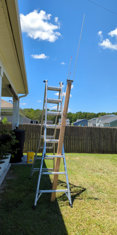
I’ve had the antenna up a handful of times since we’ve been in the house, but most of my operating has been outside, so any RF-induced problems there might have been in the house have generally gone unnoticed (except maybe for the time the Nest thermostat died). I’m pretty sure the issue is because most of the antenna lays on top of the roof and on the side where most of the wiring is (electrical service entrance, breaker panel, network router, AC unit, etc). Running 100W is probably causing a lot of RF to be coupled into the house wiring.

So it looks like I’ll have to work on changing the antenna situation. Moving the antenna and mast to the fence on the other side of the house would probably get the antenna far enough away to solve most of problem, but then I wouldn’t be able to use the coax running through the conduit without making the coax run a whole lot longer. The mast would also be on the street side of the house making it even more visible when set up. I could also order a ton of ferrite chokes to put on pretty much any current carrying wire in the house (that could get pretty expensive). I guess I could also take my operations portable and head out into the field or a park.

Another Astatic D-104 microphone

An Astatic D-104 microphone was my final, last-minute purchase from the Shelby Hamfest. We were walking to the gate heading out when I spotted a table I hadn’t visited off to the side and decided to wander over to have a look. The D-104 on the table naturally caught my eye, and decided to grab it.

Another Astatic D-104 microphone
Another Astatic D-104 microhone
Another Astatic D-104 microphone

This one was missing the bottom cover plate, and the microphone connector was removed. Looked like there might have been some re-wiring done at some point and two of the wires from the cord are unconnected, unlike my other D-104 microphone. The electrical tape on the wires connecting the microphone element suggests that maybe it was replaced at some point as well.

D-104 microphone element

At least there’s no rotting foam in this one. The microphone element housing is also a little different from my other one. This one is basically just a ring with some bits of foam supporting the microphone element while my other D-104 is more case-like.

I’ll have to see what I can do about finding or making a new cover plate for this microphone.

Tempo S1 FM transceiver

I can finally get around to some of the things that have been sitting in boxes in the garage for the last year or so.

Here we have a Tempo S1 handheld 2m FM transceiver that’s had some obvious modifications done to it. The battery pack was replaced with a car power adapter, the original telescoping antenna was replaced with a BNC connector and, based on photos of other Tempo S1 units I’ve seen online, the earphone and antenna jacks have been replaced.

Frequency selection is done by setting the thumb wheel switches to the desired frequency. A slide switch for the 1 kHz place lets you select 0 or 5 kHz, giving the radio 5 kHz tuning steps. In the photo, the radio is currently tuned for 145.690 MHz. To get 145.695, you’d slide the switch over to the +5k position.

Getting inside the unit is a simple matter of undoing 4 somewhat rusty screws. The back lifts off to reveal the radio guts and the battery compartment where the car power adapter was wired in.

Tempo S1 handheld FM transceiver power connection

According to the manual, an 8 cell NiCad battery pack providing 9.6V fit into that space. Charging the battery was done by plugging an external charger into the 1/8″ jack next to the offset selector switch.

The radio guts consist of two circuit boards. One appears to handle the RF side of things, while the other one looks like it handles the controls. It’s quite the nest of wires inside.

There’s a single IC on the board with a sticker labeled NIS-103, which I’m guessing might handle generating DTMF tones from the keypad on the front. A few wires have been soldered directly to the legs of the IC so whatever it is, removing it won’t be easy to do.

Tempo S1 handheld FM transceiver integrated circuit

An inspection of the components on the boards didn’t reveal anything that was obviously problematic. Lots of tantalum capacitors and a few electrolytic caps, but they looked fine.

Didn’t have 9V handy to connect to the power leads but I did have a 12V battery pack, so I connected that to the radio and turned it on. The radio came alive with static, which seemed like a good sign. Didn’t try anything else with the radio. I’ll work on making up a suitable connector so I can attach a 9V battery or find a suitable replacement battery pack for future experimenting.

Given the radio doesn’t have any CTCSS capability, it might be of limited use with repeaters these days unless they don’t use CTCSS tones. Still should be useful for simplex communications though.