Playing with the antenna analyzer

Finally got around to playing with the antenna analyzer I picked up at the Atlanta Hamfest. Came with batteries installed and a wall wart so it was ready to go out of the box. First thing I tried out were the inductance and capacitance measurements. Grabbed random wire wound inductor out of the junk box and put it against the antenna connector.

Random inductor on the MFJ 259B

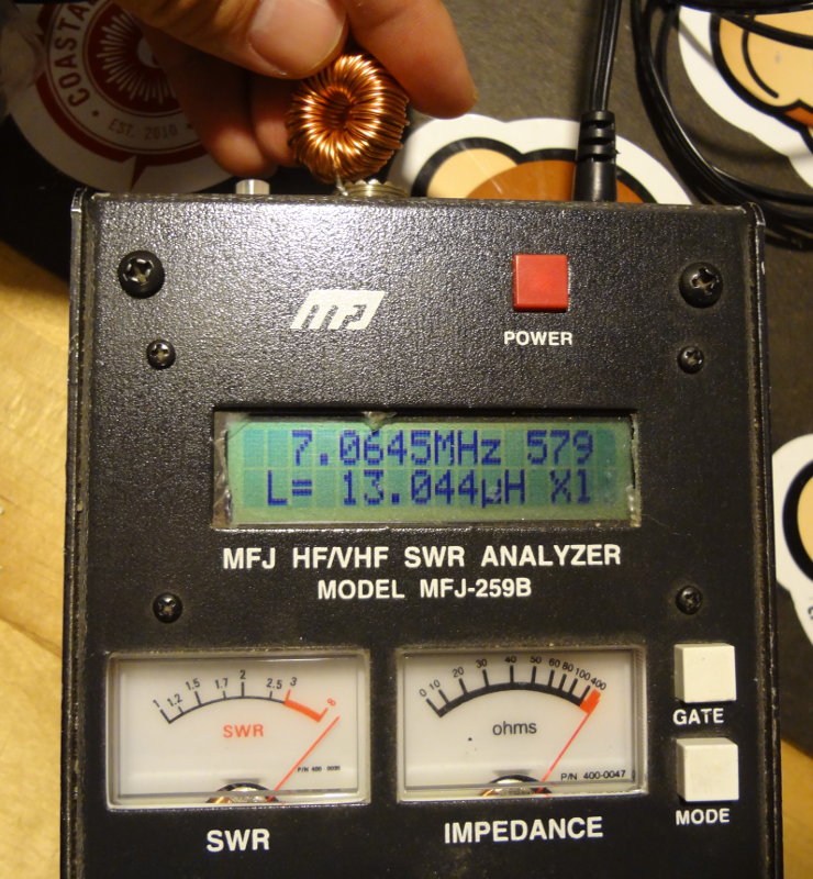
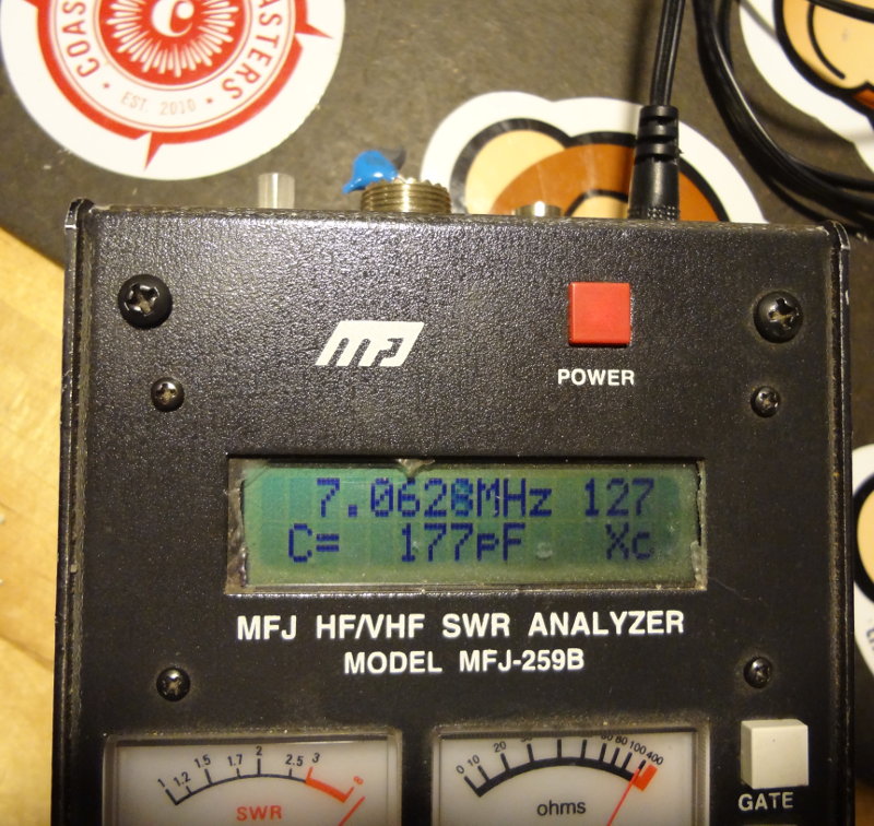
13 μH at 7.06 MHz. A pretty decent amount of inductance. It’s got a lot of windings and came out of a dead laptop power supply I think. Next I put a random capacitor on it. Capacitance meter told me it was around 216 pF. At 7.06 MHz, the analyzer measured 177 pF. Not too far off and something that I might expect at high frequencies.

Random capacitor on the MFJ259B

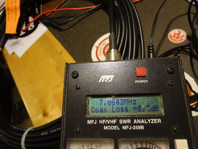
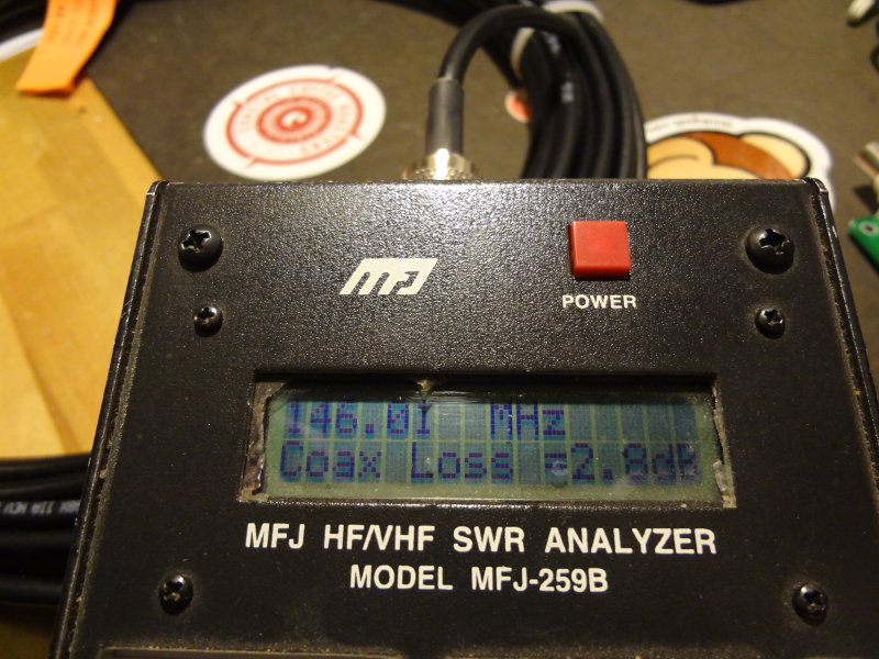
The analyzer will also measure the amount of coax loss at different frequencies. Put a 75′ length of RG-8X to see what I’d get. At 7.06 MHz, a respectable 0.3 dB loss. At 146 MHz, though, 2.8 dB. Will have to make sure to keep the coax relatively short for whatever VHF/UHF antenna I decide to build.

Coax loss with the MFJ256B
Measuring coax loss at VHF with the MFJ256B

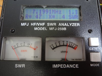
Time to bring it in and try it out on the antenna. I know the antenna works really well on the 40m band, and the analyzer confirms it. SWR of 1.1 and 50Ω impedance at around 7.2 MHz, pretty much smack dab in the middle of the band. SWR ranges from 2.1 to 1.5 across the band.

Measuring the antenna with the MFJ259B

Next I want to go through and record some more detailed measurements about the frequency performance of the antenna and maybe graph some things out. I’m sure that will look interesting.

I wonder what the analyzer will tell me about my HT antennas…Analyze ALL THE THINGS!

Almost invisible

From the street, the antenna is practically invisible against the trees, aside from the white rope used to secure one of the wires (and sometimes even that’s hard to spot).

Invisible antenna
Invisible antenna

Both ends of the antenna float, with tension provided by a couple of surplus weights

Weights
Weights
Weights holding down the antenna rope

Coax goes up the house to the eaves where it meets up with the ladder feedline of the antenna

Antenna feed line
Antenna feed line

From the other side, the antenna and ropes are a little more visible against the sky

Antenna in the air
Antenna in the air

Securing the antenna

After a week of being temporarily tied to trees and bushes, I finally got around to anchoring the antenna a little more securely using some eye screws. In the process I was able to raise the center of the antenna up another couple of meters which might help things.

One arm of the antenna is weighted down with a 2lb weight and floats up and down so that it can move with the trees. The center and other leg are tied down with enough slack to handle windy days. I may change them so that they’re just weighted down as well rather than tied off.

The coax got routed through the crawl space so I won’t have to worry about running over it with the lawn mower. It runs up the side of the house through another eye screw to the antenna feed line. When the radios get moved into their permanent location in the office/shack, I’ll look at some floor or wall connections for the coax.

Wifi router antennas

I thought I’d see what I got out of EZNEC for modeling the three antennas on the wifi router. I treated each of them as single wires at 2.452 GHz about 1m off the ground (not the floor). Each wire was 8 cm long (0.654 lambda) spaced 8 cm apart. Radiation pattern is directed perpendicularly to the plane containing the antennas, so I have two of them pointed down (the wifi router is mounted to the side of the desk) and one pointed off to the side (there’s a power strip that gets in the way of it pointing down like the others).

EZNEC Wifi antenna
EZNEC Wifi antenna

After reading through some of the original documentation for NEC learning about the somewhat arcane input format (like MCNP, it can be pretty confusing at first), I’m liking how EZNEC simplifies and hides some of the complexity, but is still accessible if needed. When I start getting into building antennas, I might have to get a copy of it.

New antenna model

I was able to find some EZNEC model files for a G5RV antenna including the feed line and tried to modify it to match my current antenna setup. 40m and 80m are pretty much the same, but the radiation patterns for 20m and 10m become a little more complex compared to my initial model.

10m

EZNEC G5RV 10m
EZNEC G5RV 10m

20m

EZNEC G5RV 20m
EZNEC G5RV 20m

Here’s EZNEC’s SWR plot

EZNEC G5RV SWR plot
EZNEC G5RV SWR plot