After a week of being temporarily tied to trees and bushes, I finally got around to anchoring the antenna a little more securely using some eye screws. In the process I was able to raise the center of the antenna up another couple of meters which might help things.
One arm of the antenna is weighted down with a 2lb weight and floats up and down so that it can move with the trees. The center and other leg are tied down with enough slack to handle windy days. I may change them so that they’re just weighted down as well rather than tied off.
The coax got routed through the crawl space so I won’t have to worry about running over it with the lawn mower. It runs up the side of the house through another eye screw to the antenna feed line. When the radios get moved into their permanent location in the office/shack, I’ll look at some floor or wall connections for the coax.
I was tuning around the radio last night while waiting for Fedora 18 beta to install on the computer and heard 9A9A from Croatia calling loud and clear. He had quite the pileup going and it was interesting listening to him work everyone. A little while later after the pile up cleared away, I called him and managed to get him on the first attempt. First contact with the new antenna and it was a DX from almost 7900 km away! His signal was easily 59+ like he was next door, and I got a 59 back from him.
About 40 minutes later, I heard UT2IJ in the Ukraine calling and working a pileup too. Rather than wait, I responded and managed to work him on the first try too from 9100 km away! His signal was pretty good, a 58 and I got a 57 back.
Finally got around to starting one of the Softrock radios I got a few months ago. Decided to start with the Softrock Lite II receiver since it was the easiest and didn’t have too many SMT components to put on. Most of the components are through-hole, with a few SMT capacitors, ICs and an op amp. Perfect for starting off with SMT work.
It’s a pretty easy build, and the build instructions are pretty thorough and informative. The instructions break up the build into the different sections of the radio, explain what it does and provides the schematics, list of parts, where to put them on the board and tests afterwards.
I did run into a couple of problems with getting the SMT capacitors on. One of them was the wrong one (didn’t take note that one set was marked and the other wasn’t), and two of them I put in the wrong orientation because I wasn’t paying attention to the diagram. Other than that the SMT work turned out to be a little easier than I thought it would be.
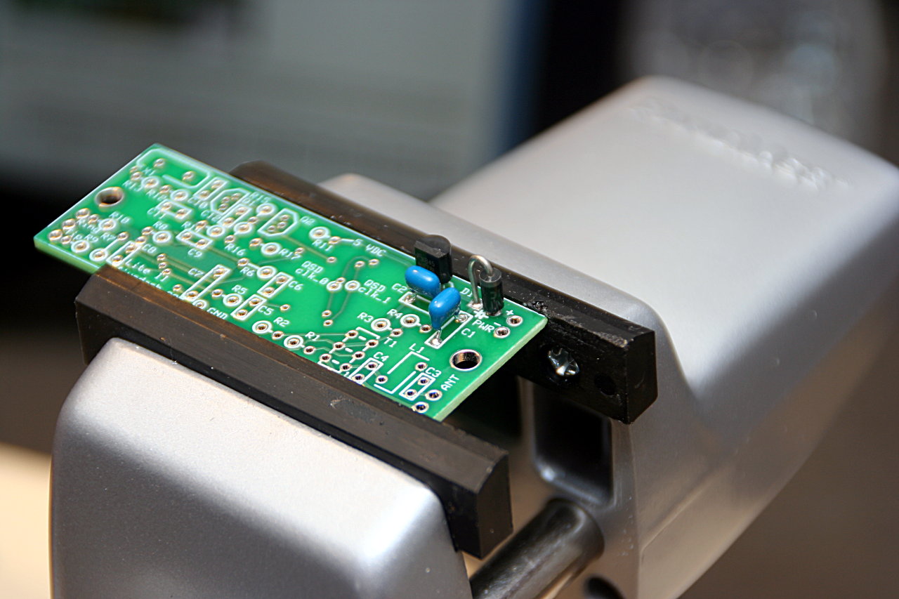
The build starts with the power supply part of the radio. All through hole stuff, except for one SMT capactior, so pretty easy. Just need to pay attention to the orientation of the diode.
Softrock Lite II power supply
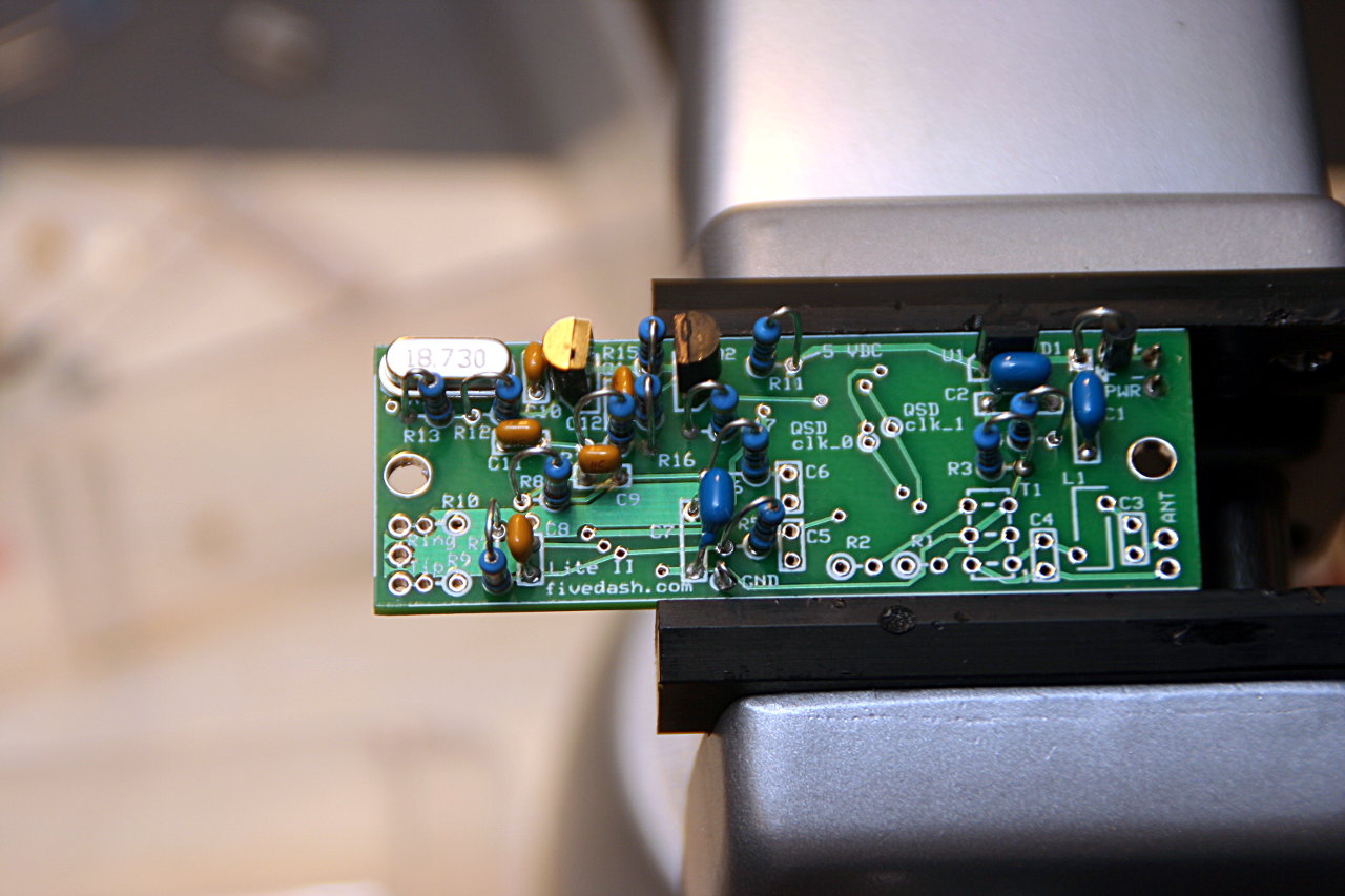
I used a couple of jumper pins and used power from the MiniLab to supply power to the radio for testing. The oscillator part was next. Again, all through hole stuff and one SMT capactior here for this section of the radio.
Softrock Lite II oscillator section
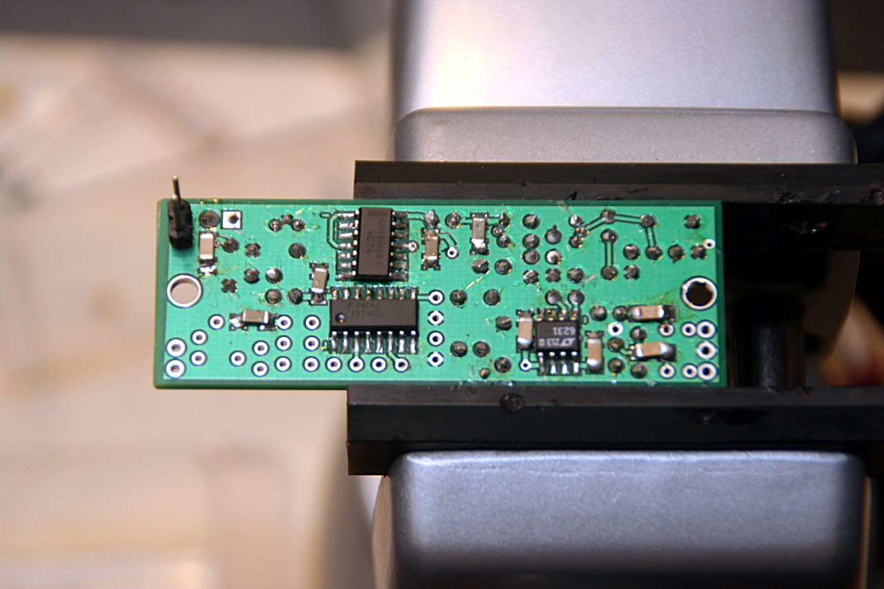
Most of the SMT components are in the divider and op-amp stages of the build. There are 3 SMT ICs and the rest of the SMT capacitors that go on in this part. With a bit of practice from the first two SMT capacitors, getting the rest of the capacitors on wasn’t too hard (aside from not paying attention to orientation). The SMT ICs and op amp were a little trickier, but still not as bad as I expected.
Softrock Lite II divider stage
Softrock Lite II SMT ICs
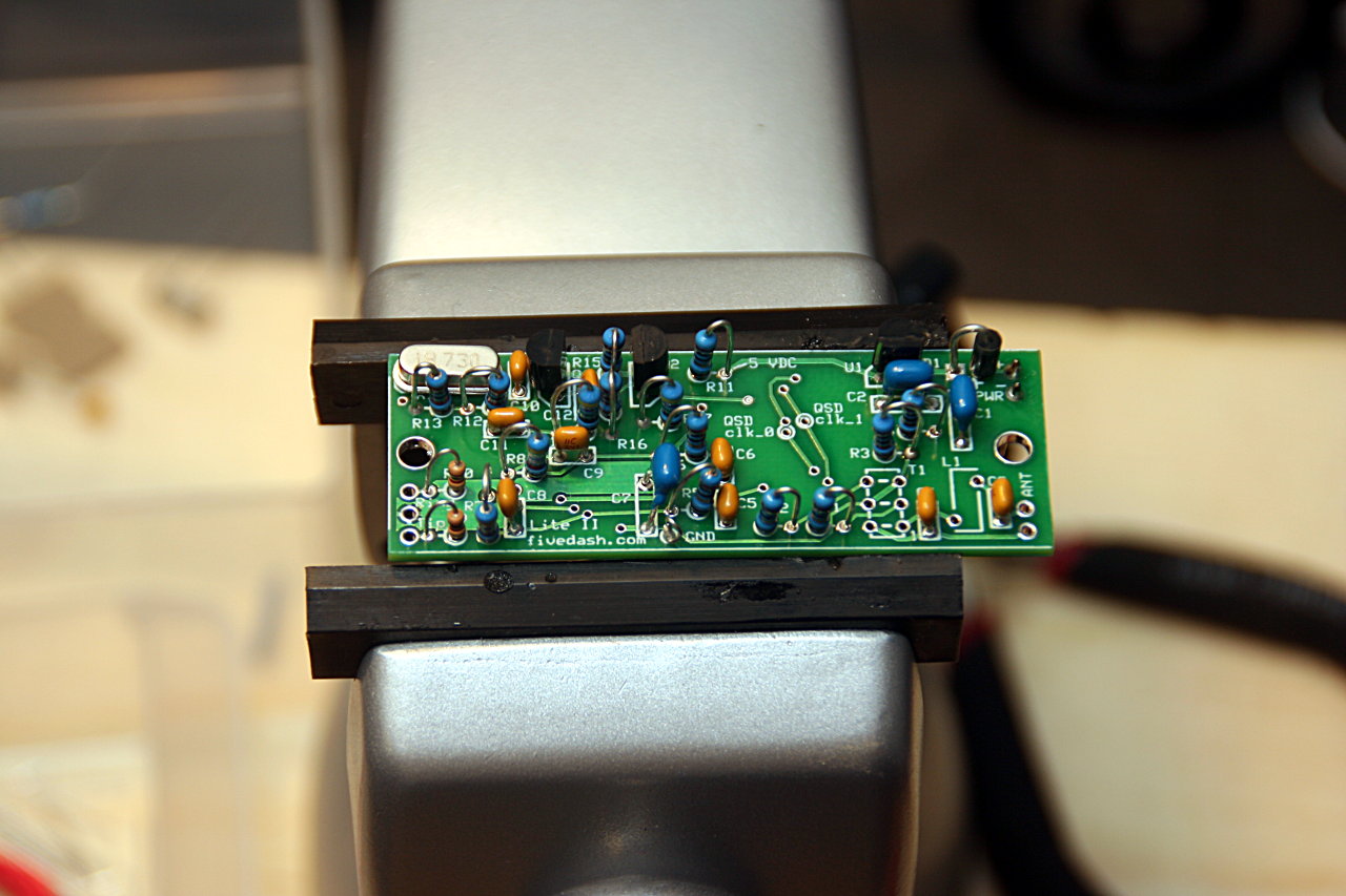
Except for the inductor and transformer in the band pass filter stage, all the components are on the radio. Will need to study the section on winding toroids first before I try to make them. Then I’ll have to switch out the jumper pins for a more permanent power connection and then make up the computer and antenna connections.
The Charleston Hamfest is only a few weeks away on Feb 2. This will be the second hamfest that I’ve gone to so I’m looking forward to seeing what will be there. The first hamfest was the Atlanta Hamfest back in June (which is also where I passed the ham radio license tests) and was a lot of fun. A pretty decent attendance and a lot of neat looking gear. I wonder what this one will have.
I thought I’d see what I got out of EZNEC for modeling the three antennas on the wifi router. I treated each of them as single wires at 2.452 GHz about 1m off the ground (not the floor). Each wire was 8 cm long (0.654 lambda) spaced 8 cm apart. Radiation pattern is directed perpendicularly to the plane containing the antennas, so I have two of them pointed down (the wifi router is mounted to the side of the desk) and one pointed off to the side (there’s a power strip that gets in the way of it pointing down like the others).
EZNEC Wifi antenna
After reading through some of the original documentation for NEC learning about the somewhat arcane input format (like MCNP, it can be pretty confusing at first), I’m liking how EZNEC simplifies and hides some of the complexity, but is still accessible if needed. When I start getting into building antennas, I might have to get a copy of it.