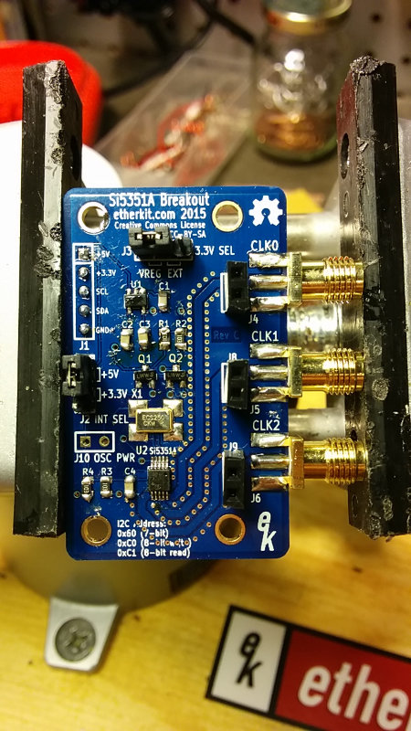
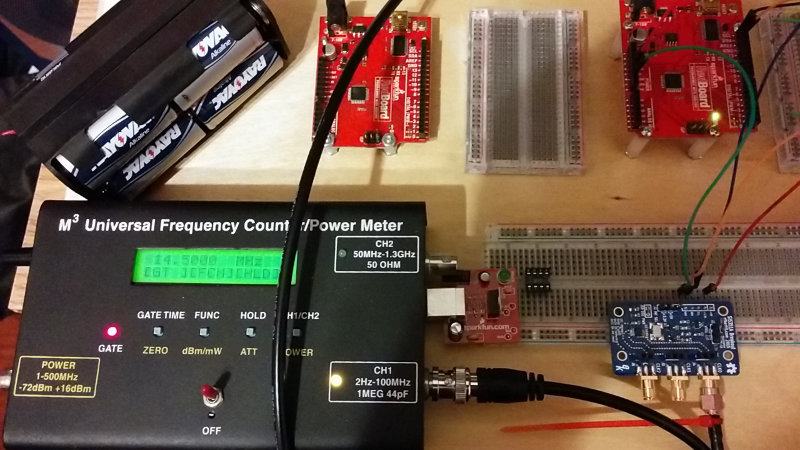
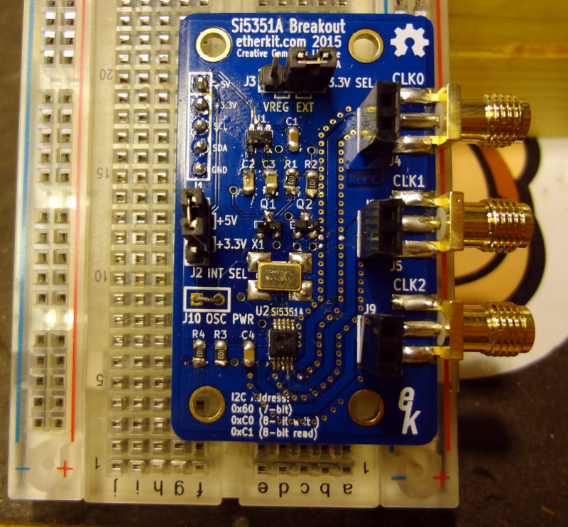
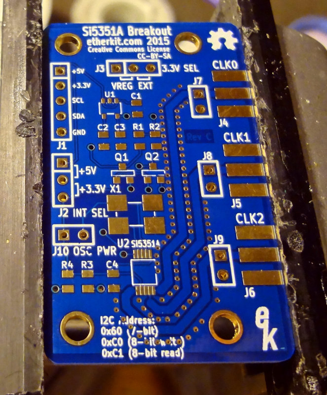
The Si5351 breakout boards all work, at least according to the frequency counter, so I thought I’d put the oscilloscope on one to see what was coming out. I just connected the output of the Si5351 board straight to the oscilloscope using an SMA/BNC pigtail. I’m sure it’s a totally incorrect way of doing it, but all I wanted to see was if I got a waveform and if it changed when I changed the Si5351 frequency.
I’ve been told that the Si5351 output is a square wave, and at kHz frequencies, that’s what I get. This is the 10 kHz waveform. Nice looking square waves.
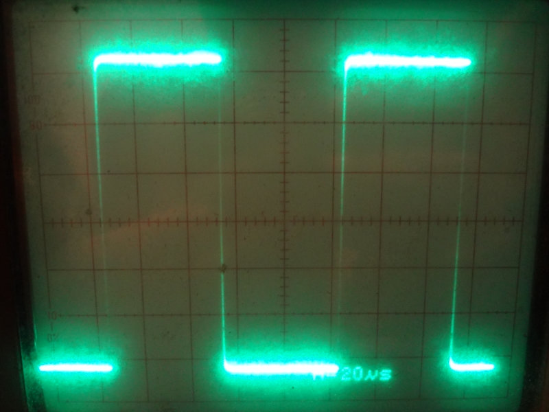
Going up a few orders of magnitude to 1MHz, the shape of the waveform loses its squareness, most likely due to the way I’ve connected things (impedance mismatch, improper loading and all that). But, as the time base shows, it’s a much higher frequency signal.
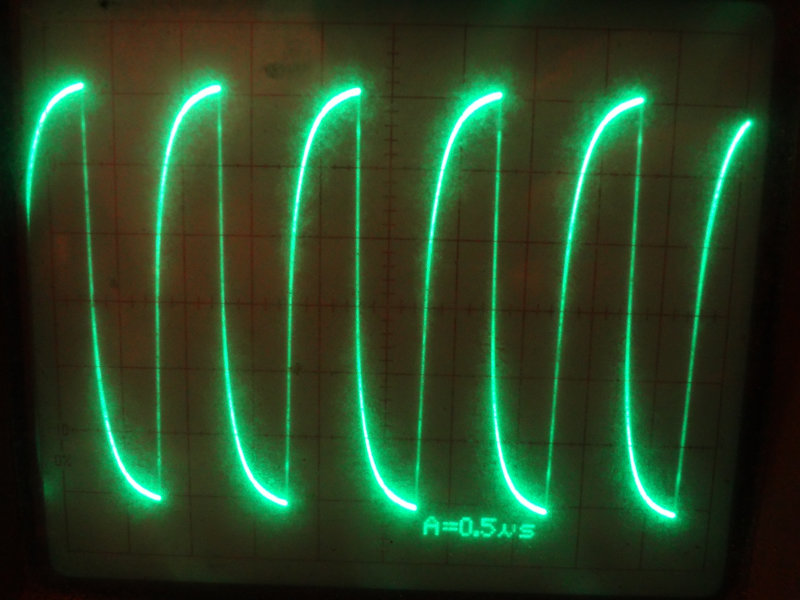
At 10 MHz, there’s even more distortion of the waveform, but definitely higher frequency.
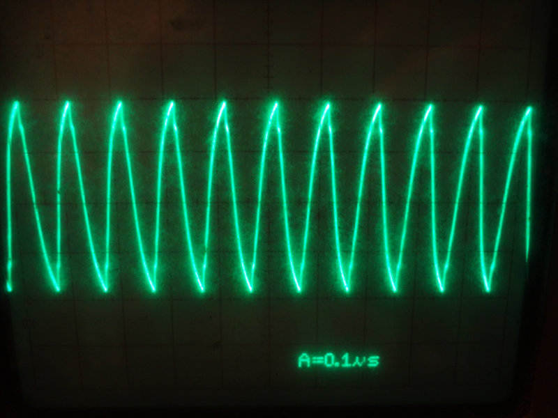
Up at 20MHz, things are looking pretty triangular.

So, TIL:
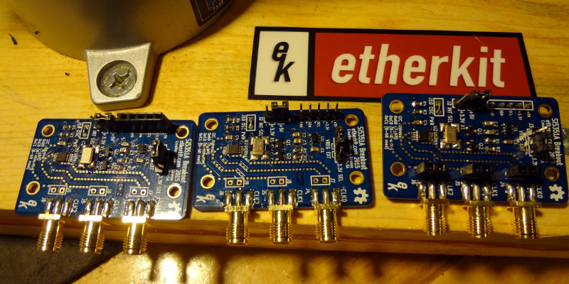
- My Si5351 board really works! Yay!
- You can’t just connect things willy-nilly to an oscilloscope and expect good results. (I already knew this, just wasn’t important for this purpose.)
- There are still some things I need to learn about using this particular oscilloscope.