Another battery charger dissection

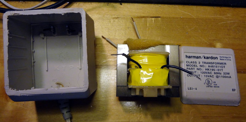
The final wall wart dissection (for now) is a dead charger for the battery of a 14V cordless drill. Rated at 18VDC out, this one is just a wall wart that plugs directly into the battery.

Cordless drill charger

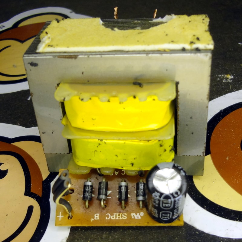
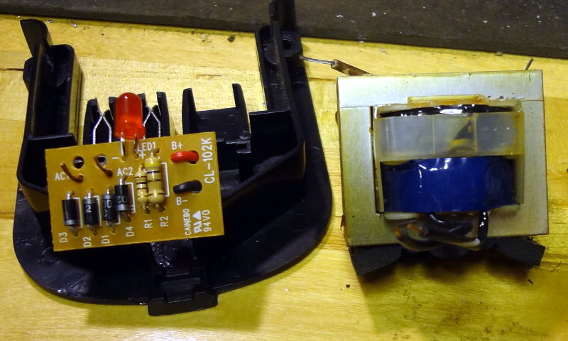
Like the previous wall wart, it consists of a large transformer with a simple full wave rectifier circuit. The rectifier circuit on this wall wart is attached right at the secondary of the transformer and adds a capacitor across the rectifier output to smooth out the ripple from the rectifier.

With this one, there appeared to be no continuity on either the primary or secondary side which certainly explains the 0V my DMM was giving me at the plug.

Battery charger innards

Today’s dissection was a dead battery charger for an 18V Black and Decker FireStorm battery that goes into my sander. The charger died a few years back and I came across it while cleaning out the junk box. The label says it takes 120V AC output and puts out 21.75V DC output. Putting the DMM across the terminals only gave about 3.8VDC.

Battery charger guts

Inside the part that plugs into the wall is a large transformer (right), like the previous wall wart. At the other end is the part that clips onto the battery. Inside I found a simple circuit with some diodes, resistors and an LED to indicate charging. Any time I see 4 diodes, I think “rectifier”, so I drew out the circuit based on the circuit board traces. Sure enough, I found a full wave bridge rectifier.

Checking the transformer, there was no continuity on the primary side, but the secondary side was fine. Made me wonder how I was getting the 3.8V at the charger terminals.

Based on this, I have a feeling the innards of the next wall wart on the dissection tableworkbench is going to be similar: big transformer with some rectifying circuitry to produce a “DC” output.

CRX1 audio

I managed to make a short 2 minute recording of the audio output from my CRX1. I don’t know enough Morse code to copy what was going on, and it’s going too fast for me to copy anyway. Hopefully it gives you an idea of what the CRX1 sounds like.

I’m really enjoying the simplicity of this little receiver. Attach the antenna, connect a power source and you have two knobs to turn that tune and adjust volume.

Assembling CRX1 was a lot of fun, and really didn’t take as long as I thought it would. Working on it a couple hours a day, it took me 4 days to finish. Don’t let the use of surface mount components scare you away from trying the kit out. As I’ve found out, working with SMD is actually pretty easy once you’ve got a few essential items.

Wall wart anatomy

Some wall warts, as it turns out, are pretty simple inside. This dead one from an old set of speakers, is just one big transformer inside that case. According to the label, it just takes 120VAC and transforms it down to 15VAC.

Wall wart guts
Wall wart guts

The primary side of the transformer measures fine with continuity between the two leads. On the secondary side though, my DMM gives me about 50Ω resistance between the two leads. I’m guessing that’s probably why it was discarded as dead.

It will be interesting to see what an AC->DC wall wart looks like inside.

CRX1 works! Part 2

Very happy to report that after eliminating the wall wart and connecting CRX1 to the ham shack power supply that everything works! I was able to hear a few CW QSOs happening yesterday morning and could tune around without any problems. Not entirely sure what frequencies I’m listening to though (somewhere between 7.030 and 7.034 MHz according to the specs).

Now the next step will be to figure out where to put the Astron power supply so that it doesn’t take up a huge amount of space on the workbench and so I can use it to power future experiments/builds. Might also be nice to have something like a RigRunner that’s fused and will let me connect multiple devices.