Using the EZNEC ARRL version that comes in the ARRL Antenna book, I attempted to create a simple model of the antenna as it’s currently set up.
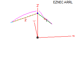
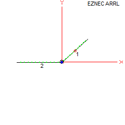
Using a tape measure and some very rough estimating, I came up with this plot of how the antenna is set up, without the ladder line in the middle (haven’t figured out how to add the feed line yet).
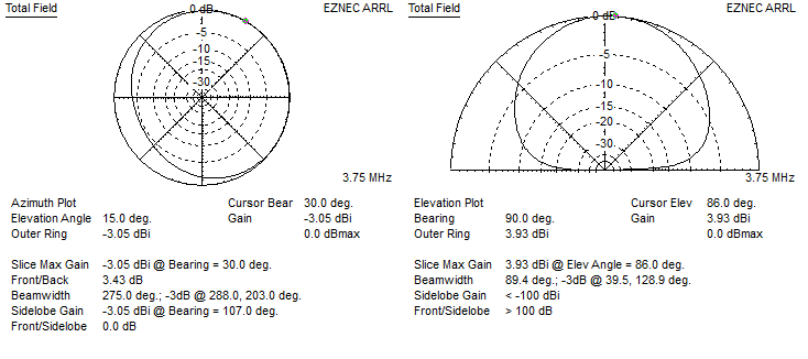
The far field plots EZNEC gives me look like this
80m
40m
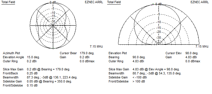
20m
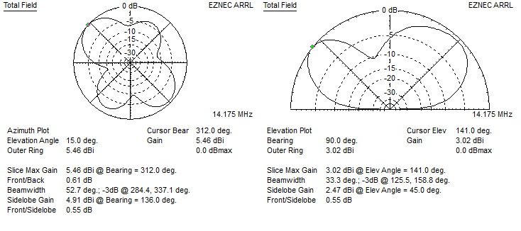
10m
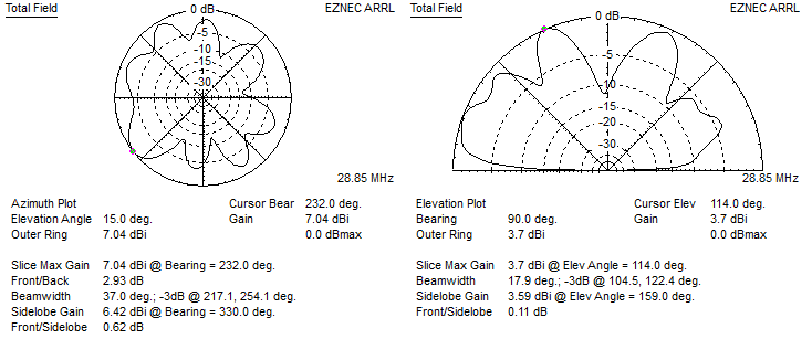
The antenna model is pretty simple and nowhere near perfect. I’m probably missing a lot by not having the feed line included. Based on these rough simulations though, it looks like I’m warming a lot of clouds (ham speak for when your antenna is sending radiation mostly straight up).
One thought on “Modeling the antenna”
Comments are closed.