I can finally get around to some of the things that have been sitting in boxes in the garage for the last year or so.
Here we have a Tempo S1 handheld 2m FM transceiver that’s had some obvious modifications done to it. The battery pack was replaced with a car power adapter, the original telescoping antenna was replaced with a BNC connector and, based on photos of other Tempo S1 units I’ve seen online, the earphone and antenna jacks have been replaced.

Tempo S1 handheld FM transceiver 
Tempo S1 handheld FM transceiver control panel 
Tempo S1 handheld FM transceiver back
Frequency selection is done by setting the thumb wheel switches to the desired frequency. A slide switch for the 1 kHz place lets you select 0 or 5 kHz, giving the radio 5 kHz tuning steps. In the photo, the radio is currently tuned for 145.690 MHz. To get 145.695, you’d slide the switch over to the +5k position.
Getting inside the unit is a simple matter of undoing 4 somewhat rusty screws. The back lifts off to reveal the radio guts and the battery compartment where the car power adapter was wired in.
According to the manual, an 8 cell NiCad battery pack providing 9.6V fit into that space. Charging the battery was done by plugging an external charger into the 1/8″ jack next to the offset selector switch.
The radio guts consist of two circuit boards. One appears to handle the RF side of things, while the other one looks like it handles the controls. It’s quite the nest of wires inside.
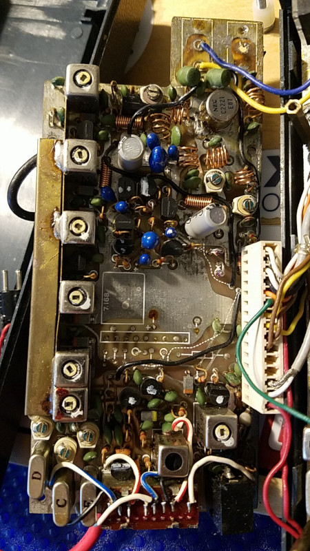
Tempo S1 handheld FM transceiver circuit board 
Tempo S1 handheld FM transceiver circuit board
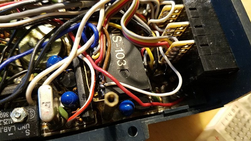
There’s a single IC on the board with a sticker labeled NIS-103, which I’m guessing might handle generating DTMF tones from the keypad on the front. A few wires have been soldered directly to the legs of the IC so whatever it is, removing it won’t be easy to do.
An inspection of the components on the boards didn’t reveal anything that was obviously problematic. Lots of tantalum capacitors and a few electrolytic caps, but they looked fine.
Didn’t have 9V handy to connect to the power leads but I did have a 12V battery pack, so I connected that to the radio and turned it on. The radio came alive with static, which seemed like a good sign. Didn’t try anything else with the radio. I’ll work on making up a suitable connector so I can attach a 9V battery or find a suitable replacement battery pack for future experimenting.
Given the radio doesn’t have any CTCSS capability, it might be of limited use with repeaters these days unless they don’t use CTCSS tones. Still should be useful for simplex communications though.