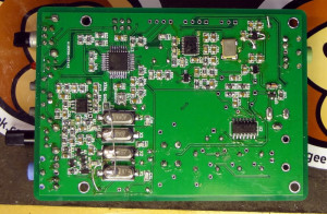
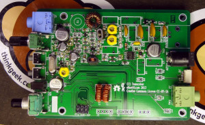
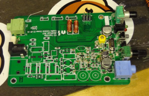
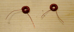
Got the last of the toroids wound and put onto the board. Now CC1 is complete!
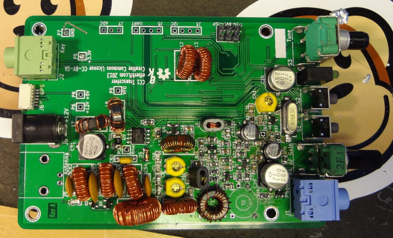

The BNC connector was put on after I snapped these photos.
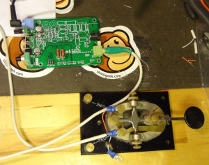
Everything sounds like it works when I apply power. I need to get a BNC/SO-239 adapter so that I can connect it to the antenna to test the receiving and then try to make myself a dummy load to test the transmit. After testing everything out, (haven’t worked out yet how I’ll test the power output, but I’ll think of something), it will be time to work on drilling holes for the end plates of the enclosure.