I’ve always liked the aesthetic of the D-104 microphones, so when I came across someone selling a couple of them at the local flea market a few months ago, I bought one of them.
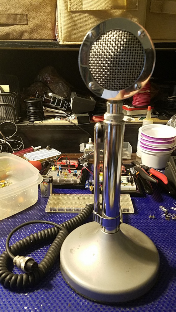
Astatic D-104 microphone 
Astatic D-104 microphone
None of my radios uses a 4-pin microphone connector, so I haven’t tried the D-104 out yet. I’ll need to make an adapter for it first.
In the meantime, time to take a look inside. I’ve read online that there are a number of modifications that can be made to the D-104, so I wanted to see what the state of this one was.
Undoing three screws allows the bottom base plate to be removed, revealing a terminal strip, the amplifier board, a volume potentiometer, and a battery. The battery was pretty dead (~4V on the DMM) but fortunately it hadn’t leaked.
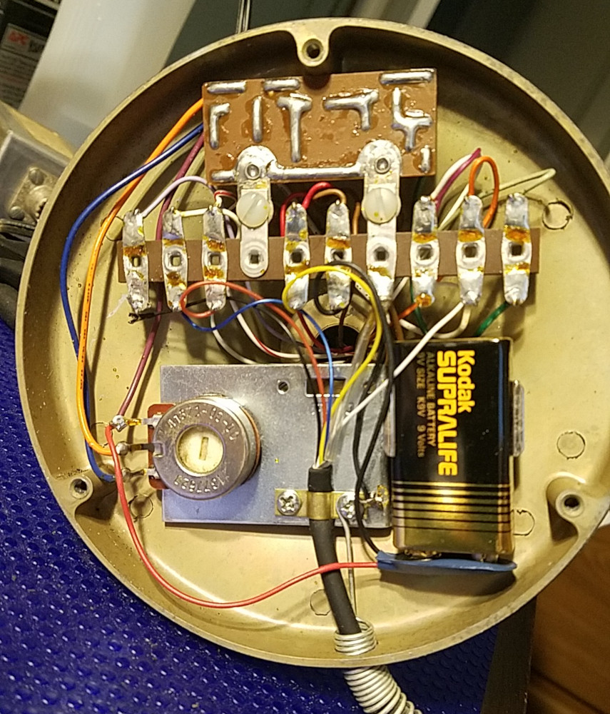
Astatic D-104 microphone circuitry 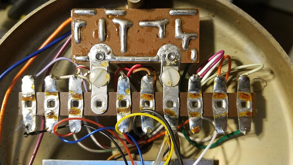
Astatic D-104 microphone circuitry 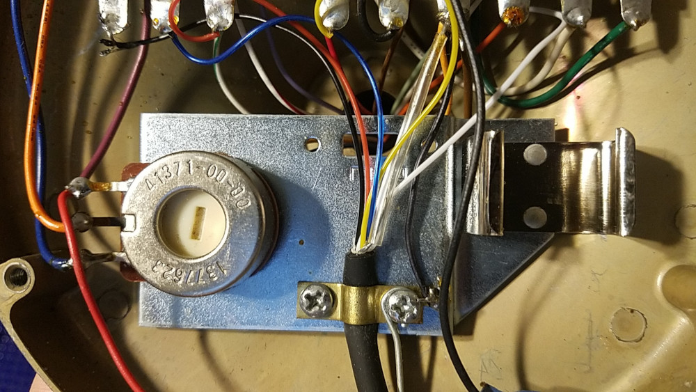
Astatic D-104 microphone circuitry 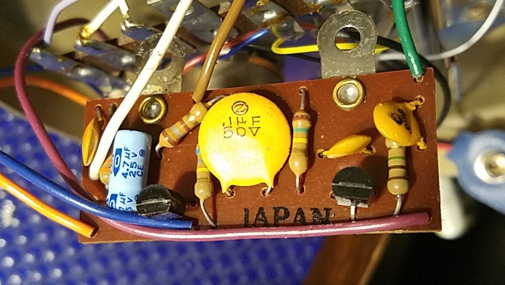
Astatic D-104 microphone circuitry
I don’t know what the innards of a D-104 are supposed to look like, but this seemed pretty stock to me.
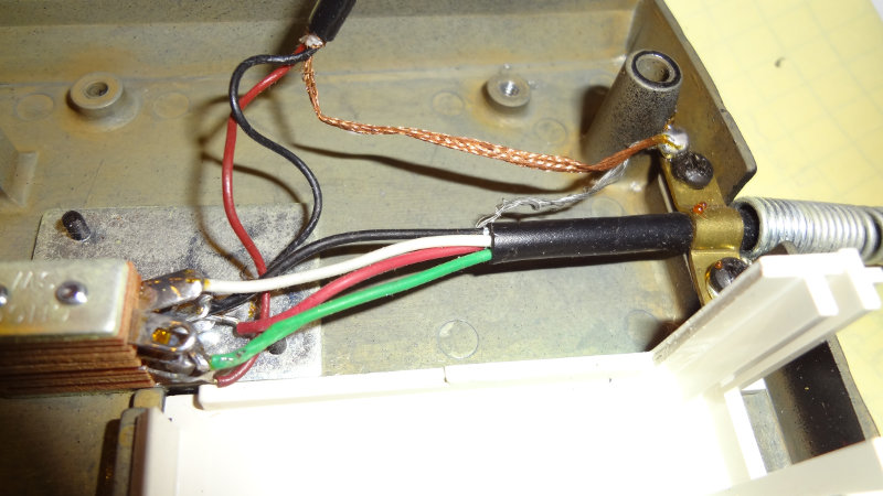
The back plate of the microphone head was removed by undoing 4 screws. The microphone element takes up most of the space inside the head. Foam attached to the back plate helps keep the microphone element in place. The foam here was pretty badly deteriorated.

Astatic D-104 microphone element 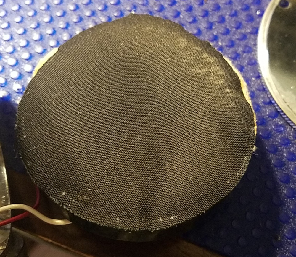
Astatic D-104 microphone element
The connections on the microphone element look pretty messy because of the rotted foam, so I might need to replace it.
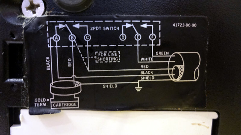
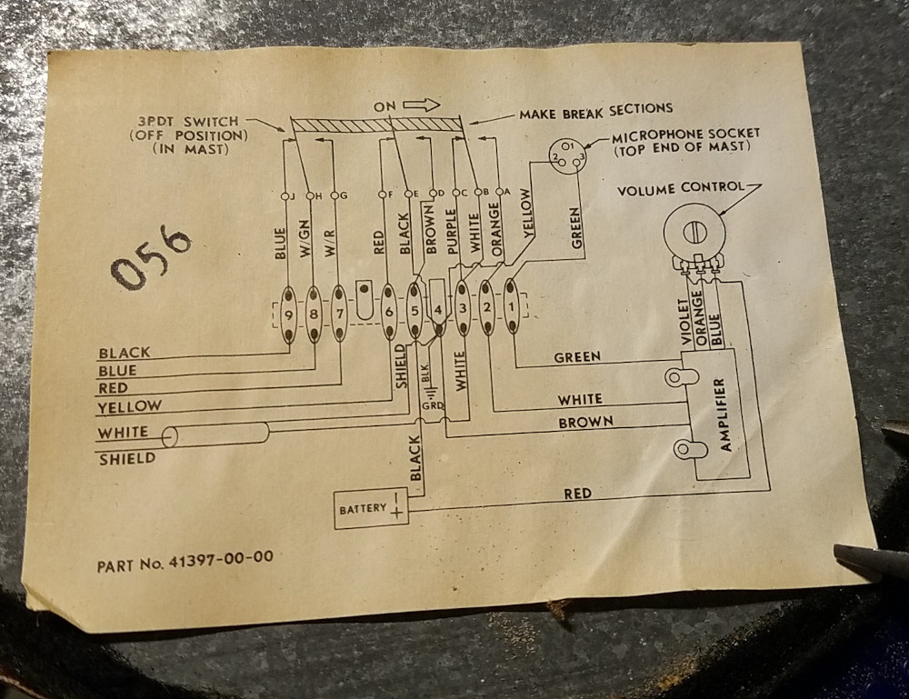
A connection diagram is conveniently attached to the base plate.
I think this will be a fun microphone to use with the radio once I get a proper connection made up (and maybe a new microphone element).