Planning on heading out to the TARC swap meet this coming weekend to see what it’s all about and maybe pick up a few things so I can get CC1 on the air. It’s up near Moncks Corner, so it’s a bit of a drive. No idea how large it is or how many people to expect to show up, but it will be a good chance to meet some more hams.
A good way to get volunteered
A good way to get volunteered to do something is to mention that something needs attention or doing. The radio club I’m a member of (CARS) is no exception.
At the last meeting, I mentioned that searching the ARRL website for clubs didn’t bring up CARS, or any of the CARS VE test sessions, to which the club president replied (paraphrasing here) “So does that mean you want to look into it?”
Sure, what the heck. I figure it will be a good chance to find out al little more about the club and get my feet wet with helping out with the club.
CC1 completed
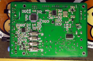
Got the last of the toroids wound and put onto the board. Now CC1 is complete!
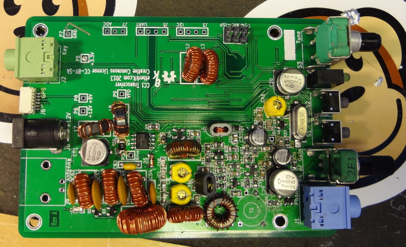

The BNC connector was put on after I snapped these photos.
Everything sounds like it works when I apply power. I need to get a BNC/SO-239 adapter so that I can connect it to the antenna to test the receiving and then try to make myself a dummy load to test the transmit. After testing everything out, (haven’t worked out yet how I’ll test the power output, but I’ll think of something), it will be time to work on drilling holes for the end plates of the enclosure.
CC1 almost complete
The CC1 kit is getting closer to being completed. All the tiny bits are soldered on, and now there’s just the toroids left to wind. I put T1 and L4/L5 on last night and now there are just 8 inductors left to wind. No lost pieces, only one extra part (which was extra to begin with) and only two fried components.
I discovered when I went to install R50 that I had accidentally installed it in the R26 position. They’re both the same resistance, but R50 is a larger resistor. In my haste, I must have just grabbed the first 100 ohm resistor that I saw and put it on. Fortunately I was able to get it off the board without too much fuss and put it where it belonged.
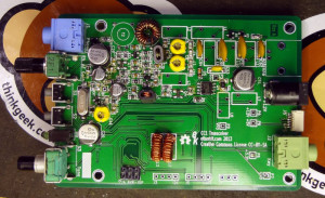
I also found that installing U2 and Q9 is a whole lot easier with lots and lots of flux on the board. Wish I had known that when I installed U1 and U5.
I better get cracking on learning Morse code!
Ham meetup? Ham-up?
Ham radio clubs can be a great place to meet other hams and to find out what’s going on in the local ham community. In the Charleston area, there are two formal clubs that I’m aware of. I’ve been a member of the Charleston Amateur Radio Society (CARS) since I got licensed, and recently learned about the Trident Amateur Radio Club (TARC).
CARS has their regular meetings on the second Monday of each month, and while the meetings are a good source of info for what’s happening in the area, they’re rather business-like and can be kind of boring. TARC meetings are on the third Monday of the month. I haven’t made it to a TARC meeting yet but from what I’ve seen on their website, their meetings seem a little more casual.
Outside of regular club meetings, I haven’t come across many other gatherings of local radio people. There’s a Monday/Wednesday/Friday breakfast meetup at the Bojangles on Ashley Phosphate. It’s a nice little meetup that I’ve had a couple of opportunities to get to when I have an excuse to be in that area for work. It’s not something I can get to on a regular basis though.
It got me thinking that it would be nice to have a regular evening or weekend gathering where local radio people can get together. There are numerous possibilities for things to do:
- talk about radio
- get on the air and play radio
- check out the newest rig
- make things
- share/collaborate on projects
- code practice
- study group for getting/upgrading your amateur radio license
- sharing radio know-how
- just hang out for some face-to-face rag chewing.
As for meeting places, it could really be anywhere. Coffee shop, someone’s garage, out in a park or field somewhere.
Anybody interested?