It took me about a little over an hour and some fumbling around with Very Small Pieces, but the power conditioning part of the CC1 transciever is done.
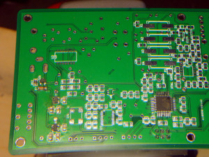
There it is in the lower left corner. 2 very small transistors and some small capacitors and resistors.
Applying 12V power gives me a good voltage at the 5 V test point, but nothing at the 3.3 V test point. I think I may have either cooked the transistor or there’s a solder bridge I can’t see. I’ll have to take it off and check underneath.
Things I’ve learned so far:
- Keep the board flat. I had one of the transistors bounce off the board and go sliding off onto the floor when I took it out of the packaging. Took me 10 minutes of hunting on my hands and knees to find it.
- I initially started with a pointed tip on the soldering iron, but found that the chisel tip seems to work better. The flat surface of the chisel tip allows you to put more heat on the component and pad than the pointed tip.
- A magnifying light is pretty much essential for this.
- Use 0.55 mm or thinner solder
- Tack one end of the component to the board with a small amount of solder. Then you can solder down the other side or other leads pretty quickly and easily.
- Go ahead and solder the barrel connector (J8) to the board. This will make supplying power for testing easier.
I’m only doing one component at a time, so it’s probably going to take me a while to finish.