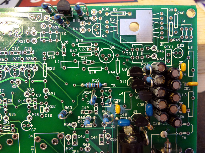
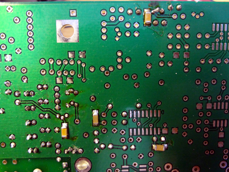
Started on the non-toroid/transformer parts of the RF I/O and switching section of the build. Nothing too difficult with this section. Four SMD capacitors on the back of the board. On top are through-hole resistors, caps, and transistors.
The holes for the transistors is pretty close together, so to make inserting them (TO-92 package) easier, use some needle nose pliers to straighten out the outer legs. The transistors slip right into the holes without having to force them in because of the bend in the leads.
The BNC connector is also attached to the board at this stage. The one supplied with my kit has an all metal body. Soldering the two ground pins to the board takes a lot of heat. I ended up having to hold my soldering iron on the pins for close to a minute before they got hot enough to get a good solder joint. I suggest doing the BNC connector last. Once you've got it soldered on, it stays pretty hot for a while.
Top and bottom of this section so far.
Off to go wind some toroids and transformers.
Comments