Finished assembling the last of the Etherkit Si5351A breakout boards I received from Jason's Indiegogo campaign. Since I had three of them to play with, I decided to do a few different configurations.
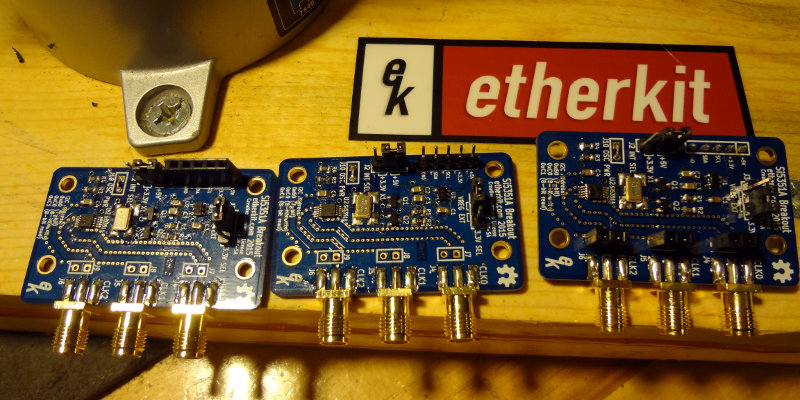
Board #1 is a pretty conventional setup with the header pins pointing up. Lays flat on a surface and could be mounted inside an enclosure if needed.
 Board #2 I used female header pins to make interfacing with my *duino boards easier, since almost all the jumper wires I have are male/male.
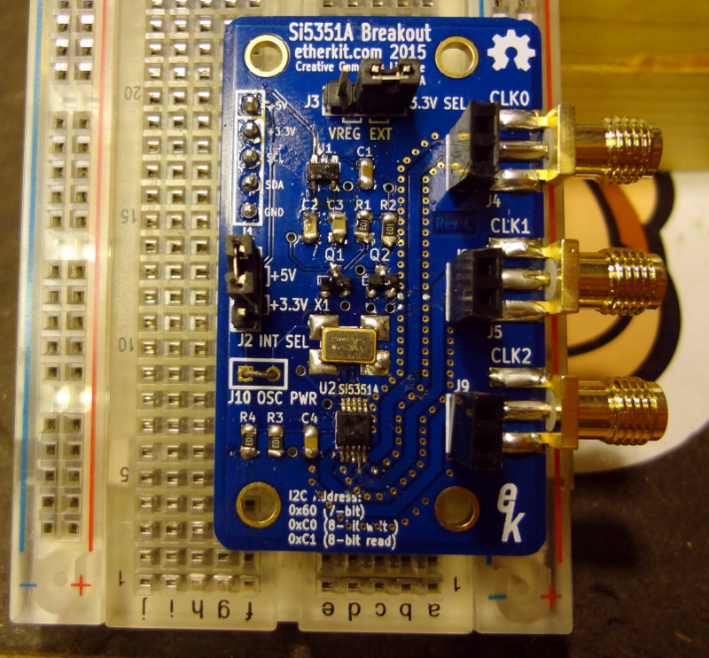
 Board #3 I set up to make it easy to use with breadboards. The header pins are pointed "down" so that I can stick the breakout board into a regular breadboard. I also added female headers to the output in addition to the SMA connectors.
 I still need to test the boards out to make sure they actually work. I think if I'm going to have any problems with the boards, it will probably be with the soldering of the Si5351A chip.
Comments